GE Multilin F650 Digital Bay Controller 1-7
1 GETTING STARTED 1.2 OVERVIEW
1
1.2OVERVIEW 1.2.1 INTRODUCTION TO 650 FAMILY OF RELAYS
This platform of relays has been designed to meet the goals that are appearing nowadays in the environment of new
substations.
Historically, protection, control and metering functions have been performed by electromechanical elements at the
beginning, then static devices, and finally by digital equipment able to integrate all these functions in a single device, called
IED (Intelligent Electronic Device).
These IEDs not only must be able to perform all functions related to system protection and control, but also, using high
speed communications, they must share information among them and send this information to control dispatch centers,
thus reducing the quantity of auxiliary elements and wiring up to 70%.
The F650 relay belongs to this new generation of devices, and can be easily incorporated in substation automation
schemes.
1.2.2 HARDWARE ARCHITECTURE
F650 units incorporate a series of interconnected modules to perform protection and control functions. Firstly, it includes a
group of AC transformers for retrieving current and voltage. These magnitudes, once digitized, are sent to a digital signal
processor (DSP), which performs metering functions and communicates with the main processor via a wide band bus. This
architecture liberates the main processor from performing real time metering, allowing a high sampling rate, of up to 64
samples per cycle, without interfering with global performance.
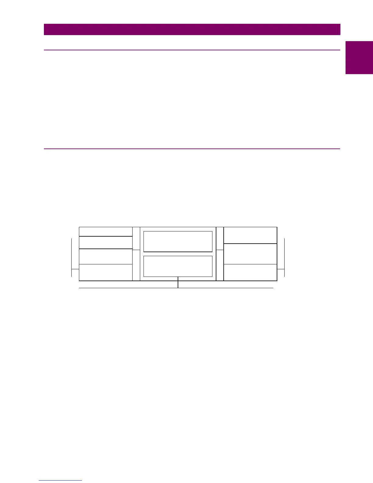
F650 relays are digital devices that include a CPU that can control multiple types of input and output signals.
Figure 1–6: F650 CONCEPT BLOCK DIAGRAM
Contact Inputs/Outputs are signals associated to physical input/output contacts in the relay
Analog Inputs are signals coming from the inputs of current and voltage transformers, used for monitoring the
power system signals.
Remote CAN Bus Inputs/Outputs: are signals associated to physical input/output contacts from independent
modules connected to the 650 unit via a fiber optic CAN Bus.
PLC: Programmable Logic Controller. Control module that enables the unit configuration (assignment of
inputs/outputs) and the implementation of logic circuits.
Protection Elements: Relay protection elements, for example: Overcurrent, overvoltage, etc.
INPUTS CPU OUTPUTS
BUS CAN
BUS CAN
LAN
Protection Elements
PLC
(logic)
Virtual Outputs
Contact Outputs
Remote CAN Bus
Outputs
Virtual Inputs
Contact Inputs
Analog inputs
Voltage & Current
Remote CAN Bus
Inputs

 Loading...


