C-10 F650 Digital Bay Controller GE Multilin
C.1 DNP 3.0 PROTOCOL FOR F650 APPENDIX C
C
C.1.4 BINARY INPUT POINTS
The F650 relay has a configurable Map of DNP Binary Input points. This map can be formed by up to 10 blocks of 16 binary
states that are configured using “Setpoint->Relay Configuration” menu from the F650PC program. The minimum number of
DNP Binary Input points is 16 and the maximum number is 160. Within these 160 DNP points, 128 bits (8 blocks of 16) are
mapped to Control Events (Setpoint->Relay Configuration->Control Events) and 32 bits (2 block of 16) are mapped to
contacts A, B of 16 Switchgears (Setpoint->Relay Configuration->Switchgear). Each Switchgear in F650 is mapped into
two DNP Binary Input points. Lets say the setting Binary Input Block1 has been set the value Switchgear 1-8, it means that
DNP Binary Input point 0 = Switchgear 1Contact A, DNP Binary Input point 1 = Switchgear 1 Contact B, DNP Binary Input
point 2 = Switchgear 2 Contact A, etc.
To each Control Event or Switchgear Contact, the user can assign any of the binary states of the F650 relay. These states
are contact inputs and outputs, virtual outputs, protection element states, PLC states, etc. DNP Points that correspond to
Control Events o Switchgear Contacts that are not configured will have a zero value in the response.
Using the PLC-Editor, through the F650PC program, selecting menu: Setpoint->Logic Configuration, it will be possible to
implement complex logic, more than simple OR and NOT previous functions. To perform this, in the menu: Setpoint->Relay
Configuration->Control Events assign a Virtual Output to selected point, after that, implement wished logic with the PLC-
Editor.
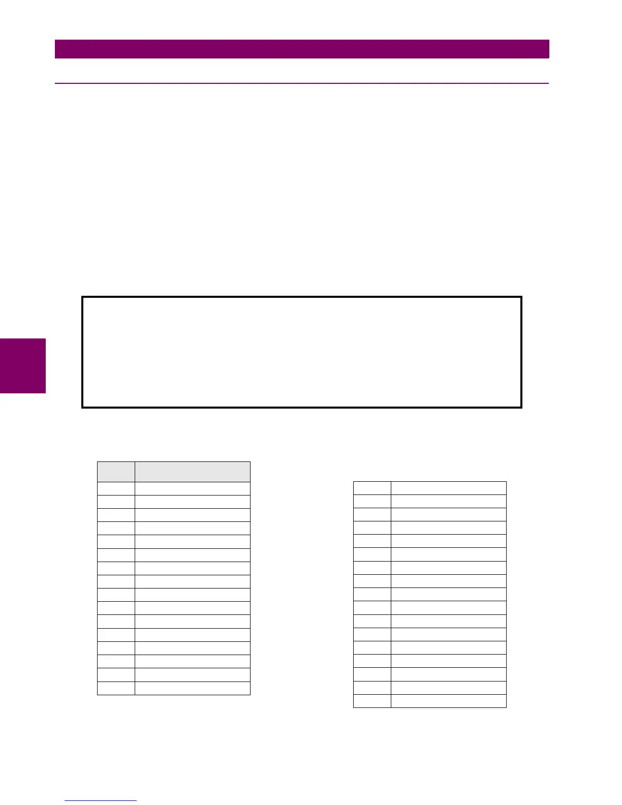
DEFAULT BINARY INPUT POINTS MAP
BINARY INPUT POINTS
Static (Steady-State) Object Number: 1
Change Event Object Number: 2
Request Function Codes supported: 1 (read), 22 (assign class)
Static Variation Reported when variation 0 requested: 2 (Binary Input Change with status)
Change Event Variation reported when variation 0 requested: 2 (Binary Input Change with Time)
Default Class for all points: 1
POINT
INDEX
NAME/DESCRIPTION
0-127 Control Events 1-128
128 Switchgear 1 Contact A
129 Switchgear 1 Contact B
130 Switchgear 2 Contact A
131 Switchgear 2 Contact B
132 Switchgear 3 Contact A
133 Switchgear 3 Contact B
134 Switchgear 4 Contact A
135 Switchgear 4 Contact B
136 Switchgear 5 Contact A
137 Switchgear 5 Contact B
138 Switchgear 6 Contact A
139 Switchgear 6 Contact B
140 Switchgear 7 Contact A
141 Switchgear 7 Contact B
142 Switchgear 8 Contact A
143 Switchgear 8 Contact B
144 Switchgear 9 Contact A
145 Switchgear 9 Contact B
146 Switchgear 10 Contact A
147 Switchgear 10 Contact B
148 Switchgear 11 Contact A
149 Switchgear 11 Contact B
150 Switchgear 12 Contact A
151 Switchgear 12 Contact B
152 Switchgear 13 Contact A
153 Switchgear 13 Contact B
154 Switchgear 14 Contact A
155 Switchgear 14 Contact B
156 Switchgear 15 Contact A
157 Switchgear 15 Contact B
158 Switchgear 16 Contact A
159 Switchgear 16 Contact B

 Loading...


