GE Multilin F650 Digital Bay Controller 3-1
3 HARDWARE 3.1 MODULE DESCRIPTION
3
3 HARDWARE 3.1MODULE DESCRIPTION
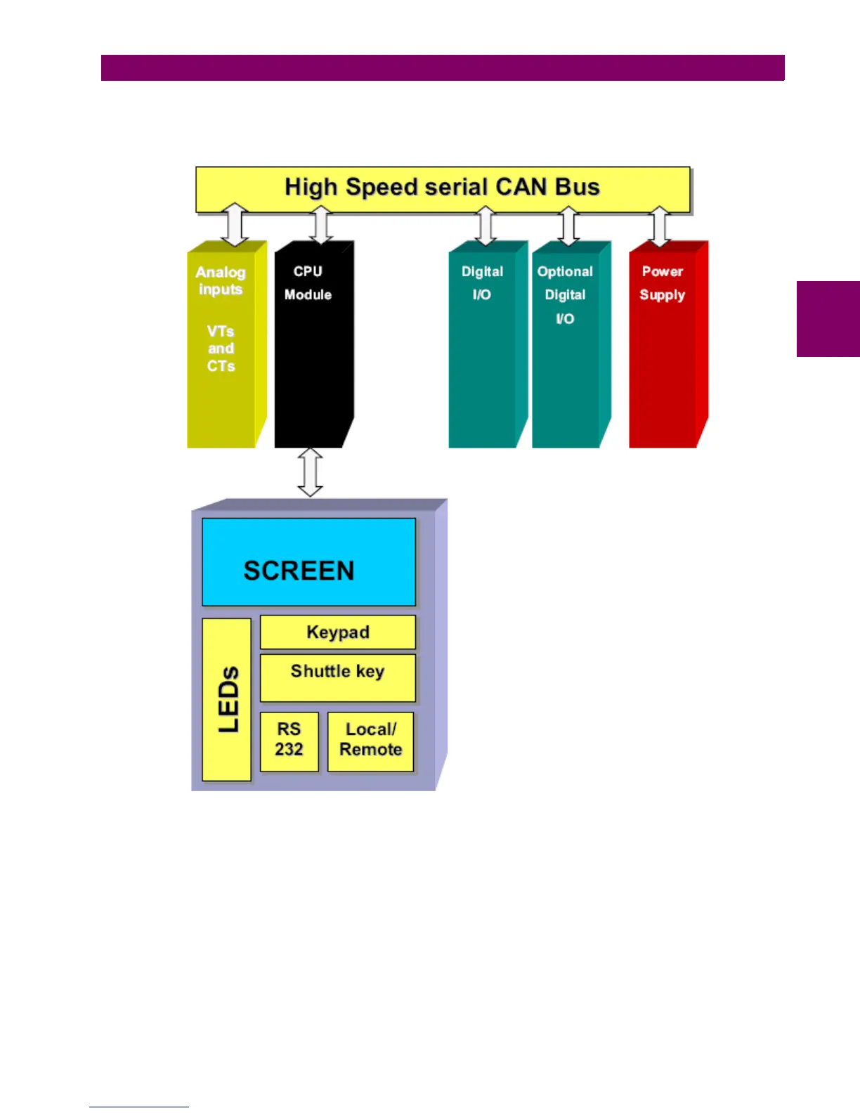
Figure 3–1: BLOCK DIAGRAM
F650 units incorporate the following modules:
• Power supply, which can be simple or redundant, depending on the selected model
• Front module with alphanumerical (4 x 20) or optional graphical (16 x 40 characters) display. It includes the bus
on its rear, which communicates with the rest of modules via a high speed CAN bus.
• Transformers module with 5 current transformers and 4 voltage transformers
• CPU including a powerful DSP for measure processing as well as synchronous and asynchronous communication
accessories.

 Loading...


