GE Multilin F650 Digital Bay Controller 5-45
5 SETPOINTS 5.4 PROTECTION ELEMENTS
5
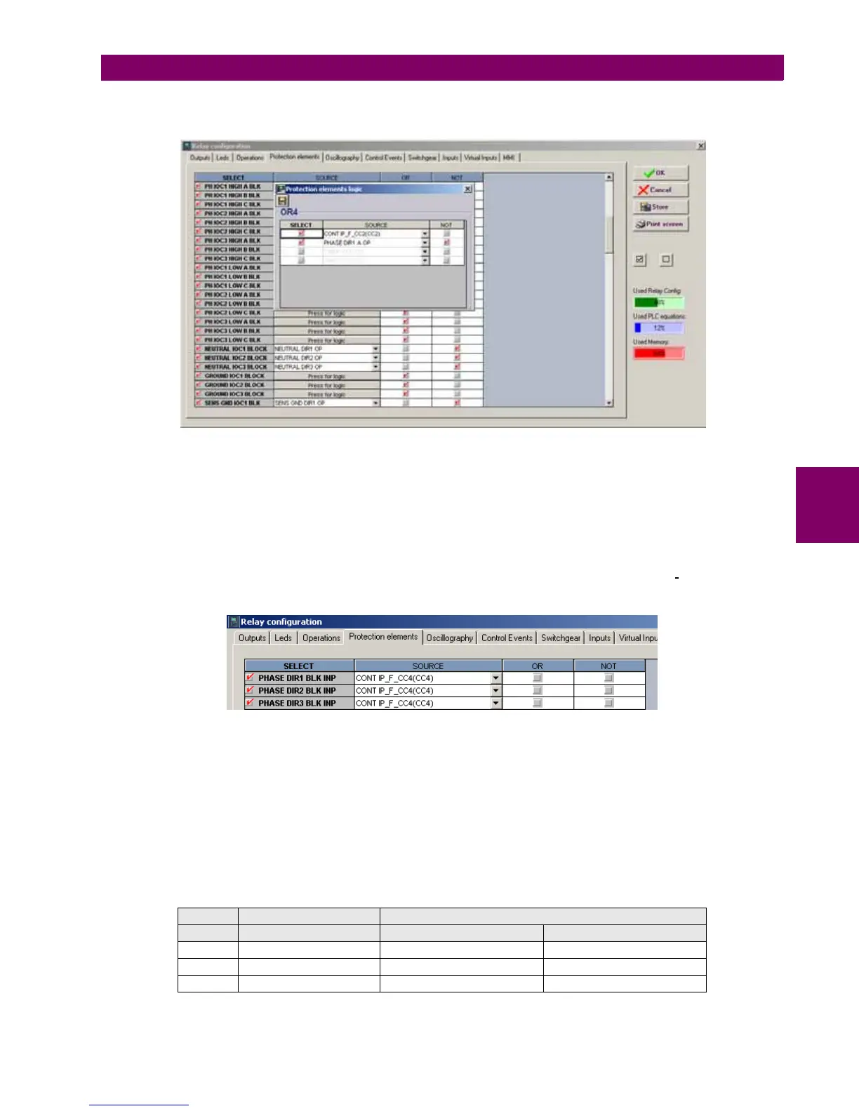
Signals used to block overcurrent units are configured at Setpoint > Relay Configuration > Protection Elements.
Figure 5–7: OVERCURRENT UNITS BLOCK CONFIGURATION BY THE DIRECTIONAL UNIT
The figure shows the block configuration for the Group 1 high range time overcurrent element. Block is configured
independently for each phase and setpoint group, and the selected block signals can vary according to the user’s
requirements. The phase overcurrent unit will be blocked when the corresponding directional unit doesn’t allow operation.
PH IOC1 HIGH A BLK = NOT(PHASE DIR1 A OP). In this example, the overcurrent unit is also blocked by a digital input.
Directional units can also be blocked with signals coming from other relays, PLCs, or through signals configured in the relay
PLC Editor (Logic configuration tool). The signal used in that case is PHASE DIR BLK INP. Figure 5–8:
shows an example
of the default block configuration of directional units by digital input. There is one block signal per input for each setpoint
group.
Figure 5–8: DIRECTIONAL UNIT BLOCK CONFIGURATION BY INPUT
The main component of the phase directional element is the angle comparator with two inputs: the operation magnitude
(phase current) and the polarization magnitude (phase-to-phase voltage rotated the angle set in MTA setpoint), which is the
torque angle.
The Polarization type used in the directional unit is crossed, this means that in case of a fault in phase A, the Operation
magnitude will be Ia, and the polarization magnitude will be Vbc, rotated the set torque angle. In case of a fault in phase B,
the operation magnitude will be Ib, and the polarization magnitude will be Vca rotated the set torque angle. Finally, in case
of a fault in phase C, the operation magnitudes will be Ic, and Vab.
Table 5–42: OPERATION AND POLARIZATION MAGNITUDES FOR DIRECTIONAL UNITS
POLARIZING SIGNAL VPOL
PHASE OPERATING SIGNAL ABC PHASE SEQUENCE ACB PHASE SEQUENCE
A IA angle VBC angle x 1 MTA VCB angle x 1 MTA
B IB angle VCA angle x 1 MTA VAC angle x 1 MTA
C IC angle VAB angle x 1 MTA VBA angle x 1 MTA

 Loading...


