GE Multilin F650 Digital Bay Controller 5-5
5 SETPOINTS 5.2 PRODUCT SETUP
5
5.2.1.5 IEC 60870-5-104
Communication setpoints for IEC 60870-5-104 protocol. For more detail information go to appendix D in this manual.
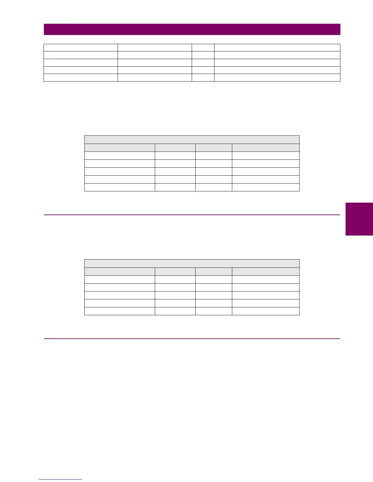
Table 5–6: IEC 60870-5-104 PROTOCOL SETPOINTS
5.2.2 MODBUS USER MAP
ModBus user map definition. 256 records, selectable from the complete relay ModBus map form the ModBus user map. For
more detail information go to appendix B in this manual.
Table 5–7: MODBUS USER MAP SETPOINTS
5.2.3 FAULT REPORT
5.2.3.1 OVERVIEW
The fault report module defines the type of fault (three-phase, phase-to-phase, phase-to-ground), and the distance to the
fault. The fault activation signal (FAULT REPORT TRIGG) is programmed at “Setpoint > Relay Configuration >
Protection Elements”.
The fault report provides fault date, fault type, fault location information, and the index of the last fault report produced
(Fault Report Number) for the last fault produced.
Information referred to the last ten faults is stored as fault report and available to the user through EnerVista 650 Setup
software or the web server application. Each fault report includes the following information:
• Fault date and time
• Pre-fault current and voltage in primary values
Binary Input Block 6 CTL EVENTS 81-96
Binary Input Block 7 CTL EVENTS 97-112
Binary Input Block 8 CTL EVENTS 113-128
Binary Input Block 9 SWITCHGEAR 1-8
Binary Input Block 10 SWITCHGEAR 9-16
PRODUCT SETUP>COMMUNICATION SETPOINTS >IEC 870-5-104
Name Default Value Step Range
Function DISABLED [DISABLED – ENABLED]
TCP Port 2404 [0 : 65535]
Common Addr of ASDU 255 [0 : 65535]
Cyclic Meter Period 0 [0 : 3600]
Synchronization Event 0 [0 : 3600]
PRODUCT SETUP > MODBUS USER MAP
Name Default Value Step Range
Address 00 0000 [0000 : FFFF]
Address 01 0000 [0000 : FFFF]
... ...
Address 254 0000 [0000 : FFFF]
Address 255 0000 [0000 : FFFF]

 Loading...


