GE Multilin F650 Digital Bay Controller 6-27
6 ACTUAL VALUES 6.3 METERING
6
6.3.3 PHASOR DIAGRAM
Actual> Metering > Phasor Diagram
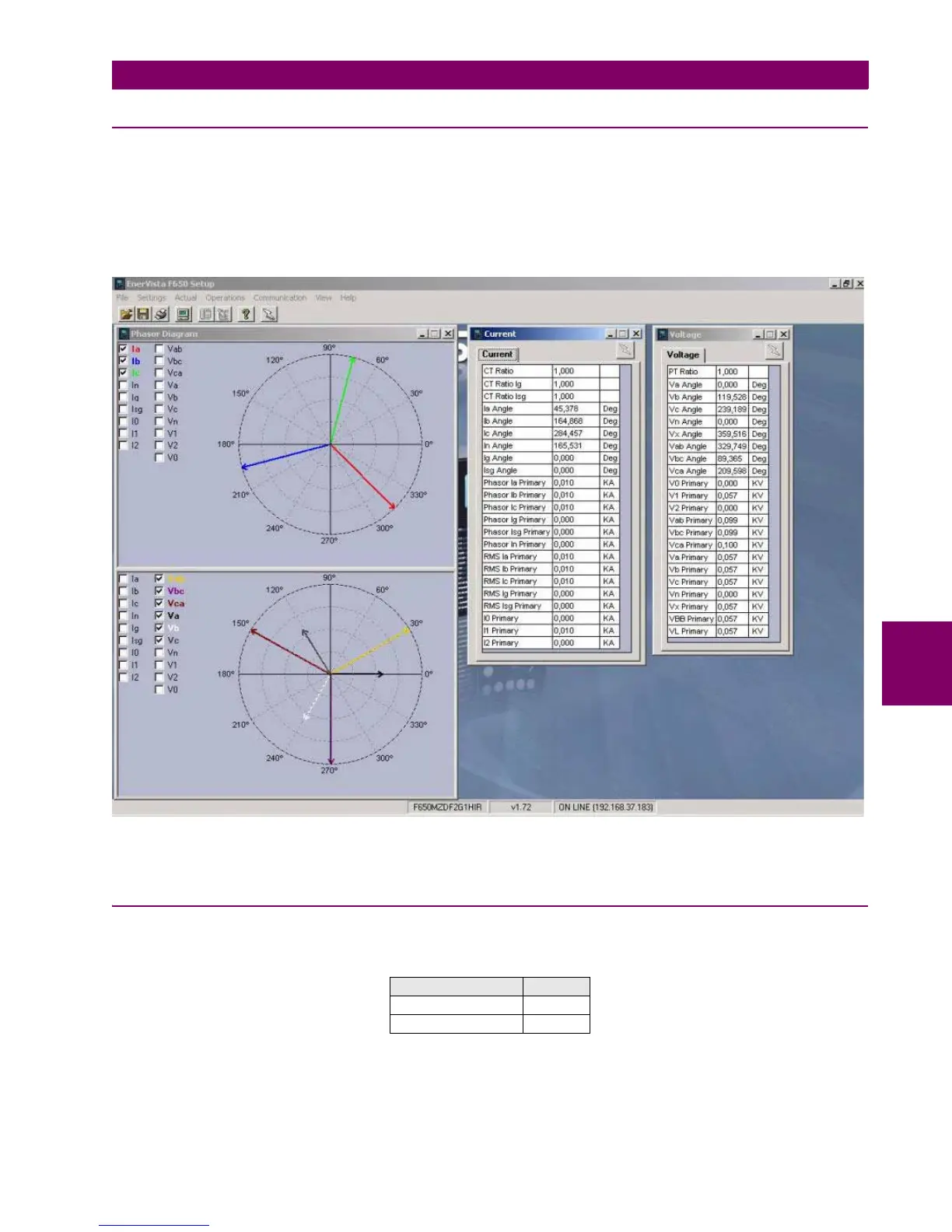
This window shows the phasors for voltage and current values, phase to phase, phase to ground and sequence values,
provided by the unit. The angles provided by the unit are clockwise, all the angles are positive values, so for a system Va
(0,0°), Vb (0,-120°), Vc (0,120°) the relay will provided the following angles Va (0,0°), Vb (0,120°), Vc (0,240°).
The following figure shows the phasor diagram provided by EnerVista F650 Setup:
Figure 6–2: PHASOR DIAGRAM
6.3.4 FREQUENCY
Actual> Metering > Frequency
Table 6–42: FREQUENCY VALUES
DESCRIPTION UNITS
Line Frequency Hz
Bus Frequency Hz

 Loading...


