6-28 F650 Digital Bay Controller GE Multilin
6.3 METERING 6 ACTUAL VALUES
6
6.3.5 INPUTS / OUTPUTS
Digital inputs and outputs are located in the same board. Depending on the relay model, the number of inputs and outputs
will vary as:
If the relay model is F650***F1*** the unit will incorporate 1 board (F) with 16 inputs and 8 outputs.
If the relay model is F650***F2*** the unit will incorporate 1 board (F) with:
8 inputs + 4 tripping coil supervision circuits and
6 outputs + 2 outputs with tripping current supervision circuits
If the relay model is F650***F*G1** the unit will incorporate a second board (G) with 16 inputs and 8 outputs
6.3.5.1 CONTACT INPUTS
Actual > Inputs/Outputs > Contact inputs > Board X (being X the corresponding board in each case).
On the inputs screen, the LED associated to the activated input will light up in green, if an input is not activated, the LED will
not light up. The “Board X Status” LED indicates the status of the board; it will be lit up if the board is correct and the
communication or the Relay model is appropriate.
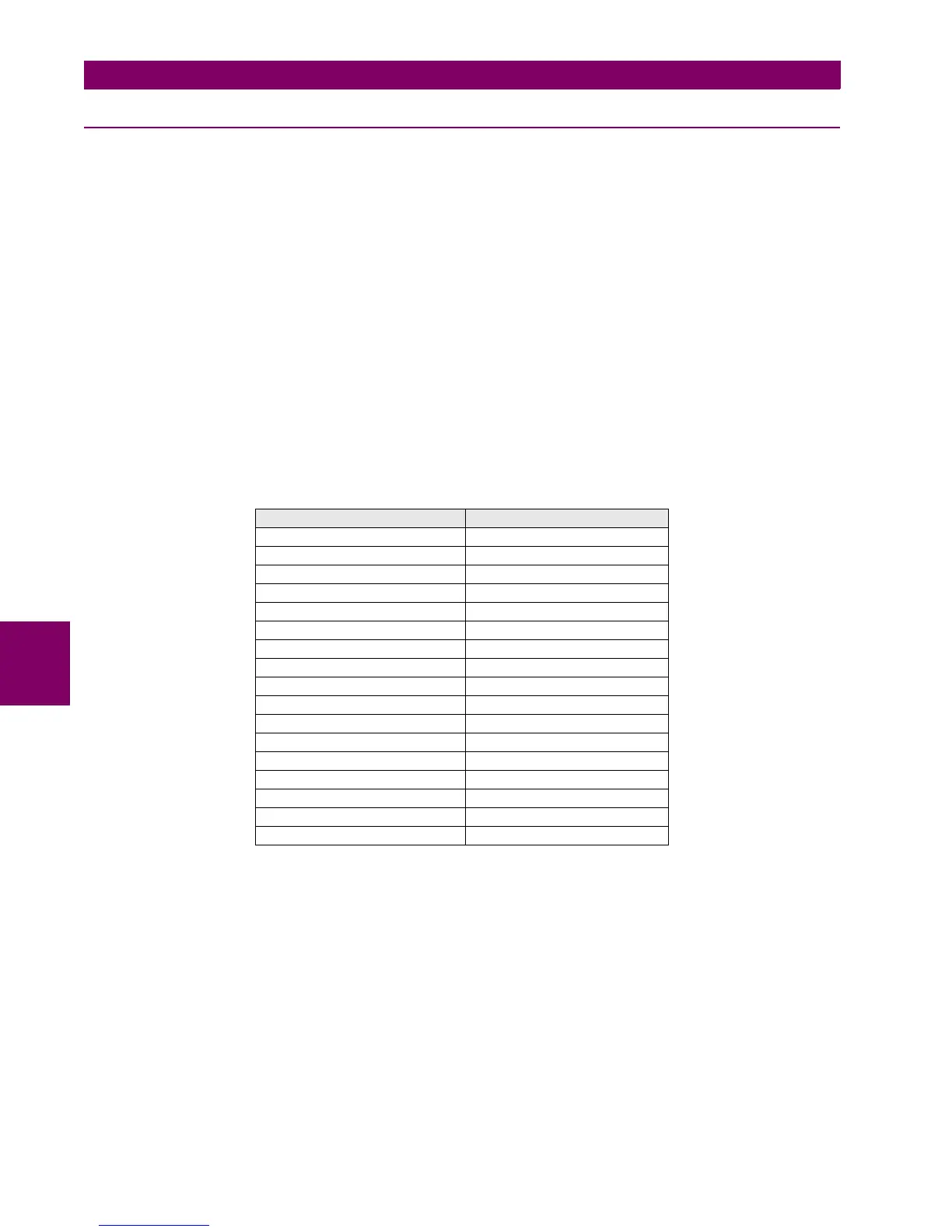
Table 6–43: CONTACT INPUTS ACTIVATION SIGNALS
CONTACT INPUTS TYPE 1 CONTACT INPUTS TYPE 2
CONT IP_X_CC1 (CC1) CONT IP_X_CC1 (CC1)
CONT IP_X_CC2 (CC2) CONT IP_X_CC2 (CC2)
CONT IP_X_CC3 (CC3) CONT IP_X_CC3 (CC3)
CONT IP_X_CC4 (CC4) CONT IP_X_CC4 (CC4)
CONT IP_X_CC5 (CC5) CONT IP_X_CC5 (CC5)
CONT IP_X_CC6 (CC6) CONT IP_X_CC6 (CC6)
CONT IP_X_CC7 (CC7) CONT IP_X_CC7 (CC7)
CONT IP_X_CC8 (CC8) CONT IP_X_CC8 (CC8)
CONT IP_X_CC9 (Va_COIL1) CONT IP_X_CC9 (CC9)
CONT IP_X_CC10 (Vb_COIL1) CONT IP_X_CC10 (CC10)
CONT IP_X_CC11 (Va_COIL2) CONT IP_X_CC11 (CC11)
CONT IP_X_CC12 (Vb_COIL2) CONT IP_X_CC12 (CC12)
CONT IP_X_CC13 (O7_SEAL) CONT IP_X_CC13 (CC13)
CONT IP_X_CC14 (O8_SEAL) CONT IP_X_CC14 (CC14)
CONT IP_X_CC15 (SUP_COIL1) CONT IP_X_CC15 (CC15)
CONT IP_X_CC16 (SUP_COIL2) CONT IP_X_CC16 (CC16)
BOARD X STATUS BOARD X STATUS

 Loading...


