GE Multilin F650 Digital Bay Controller 4-9
4 HUMAN INTERFACES 4.1 ENERVISTA 650 SETUP SOFTWARE INTERFACE
4
NOTE 1: Depending on the type of Inputs/Outputs incorporated in relay slots F and G, configuration options will be different.
There are 2 template files available for working off-line with any F650 available model:
F650_F1G0_V200.650: Board 1 in slot F and without any board in slot G.
F650_F1G1_V200.650: Board 1 in slot F and board 1 in slot G.
F650_F1G4_V200.650: Board 1 in slot F and board 4 in slot G.
F650_F1G5_V200.650: Board 1 in slot F and board 5 in slot G.
F650_F2G0_V200.650: Board 2 in slot F and without any board in slot G.
F650_F2G1_V200.650: Board 2 in slot F and board 1 in slot G.
F650_F2G4_V200.650: Board 2 in slot F and board 4 in slot G.
F650_F2G5_V200.650: Board 2 in slot F and board 5 in slot G.
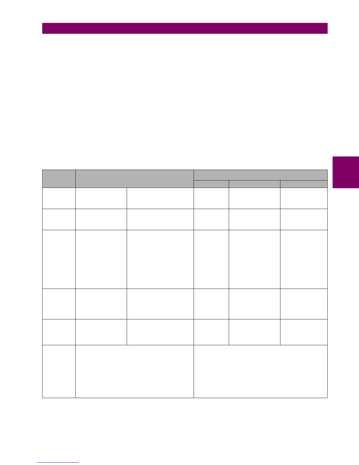
Table 4–1: TYPES OF FILES GENERATED BY ENERVISTA 650 SETUP SOFTWARE OPERATION MODE OFF-LINE:
FILE TYPE SETTINGS & CONFIGURATION FILE *.650
LOGIC CONFIGURATION FILES (*.PEP, *AUT, *.LIB)
*.PEP *.AUT *.LIB
Relevant
sections inside
the file
Protection Settings and
Configuration Section
Compiled logic equations
section
Header for
Logic project
Graphical edition
container. Logic
equations in FDB
format.
User programmable
logic objects
Created by EnerVista 650 Setup
Logic configuration graphic
editor (PLC Editor)
Logic
configuration
graphic editor
(PLC Editor)
Logic configuration
graphic editor (PLC
Editor)
Logic configuration
graphic editor (PLC
Editor)
Definition and
contents
Relay configuration file
containing all
protection elements
Settings, input/output
and LEDs
configuration, graphic
display configuration,
etc.
Equations corresponding to
the logic created and compiled
in the PLC Editor
PLC project file
containing the
necessary
information
relative to the
relay model,
logic libraries
included in the
project (*.lib),
graphic file
name (*.aut),
etc.
PLC Project file
containing all the
drawings used by the
logic, required by F650
relay based on IEC
61131-3 standard.
Functional block
diagram (FDB).
Library file to be
included as an object
in a PLC project.
Logic packages that
can be stored into
libraries and be
distributed in different
PLC projects.
File storage in
the PC
EnerVista 650 Setup:
“File>Save *”
EnerVista 650 Setup:
“File>Save *”
It is necessary to store the
logic configuration files used to
create the PLC project for
further logic modifications.
PLC Editor:
“File>Save
Project”
PLC Editor:
“File>Save Project”
PLC Editor:
“File>Save Library”
File Retrieval
of previously
stored files in
PC
EnerVista 650 Setup:
“File>Open *”
EnerVista 650 Setup:
“File>Open *”
It is necessary to have the
logic configuration files used to
create the PLC project
PLC Editor:
“
File>Open
Project”
PLC Editor:
“File>Open Project”
PLC Editor:
“File>Library>New
Library”
Basic
information
transfer mode
to the relay
Connect with the relay
(“Communications>Computer”)
Open the created file (“File>Open *”)
Send to relay from the menu: “File>Send info to relay”
Note that texts used in the configuration of inputs,
outputs, etc. are not sent to the relay. The only texts
sent to relay are operations, events, and LEDs.
Connect with the relay (“Communications>Computer”)
Launch F650 PLC Editor (“Setpoint>Logic Configuration”)
Open the created PLC project (“File>Open Project”)
Compile the project (“Run>Compile”)
Now the logic (virtual outputs) can be sent directly to relay
(“Run>Send Equations to Relay”). Texts of virtual outputs are
not stored in the relay, only in the logic configuration files to be
edited.

 Loading...


