GE Multilin F650 Digital Bay Controller 2-5
2 PRODUCT DESCRIPTION 2.3 ORDERING CODE
2
F650 units allow monitoring and configuring these I/O boards as if they were internal boards, located on slots F and G. In
this case, slots are labeled as H y J.
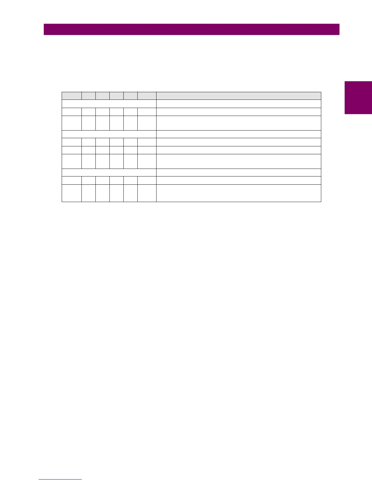
The required information to completely define a CIO Module is shown on TABLE 2-2.
Table 2–3: ORDERING CODE FOR CIO MODULE
CIO H - J - - DESCRIPTION
I/O BOARD IN SLOT H
1 16 inputs + 8 outputs
2 8 inputs + 4 circuit supervision circuits + 6 outputs + 2 outputs with
tripping current supervision (latching)
I/O BOARD IN SLOT J
0 None
1 16 inputs + 8 outputs
2 8 inputs + 4 circuit supervision circuits + 6 outputs + 2 outputs with
tripping current supervision (latching)
AUXILIARY VOLTAGE
LO 24-48 Vdc (range 19.2 – 57.6)
HI 110-250 Vdc (range 88 – 300)
120-230 Vac (range 96 – 250)

 Loading...


