5-102 F650 Digital Bay Controller GE Multilin
5.6 INPUTS/OUTPUTS 5 SETPOINTS
5
5.6INPUTS/OUTPUTS
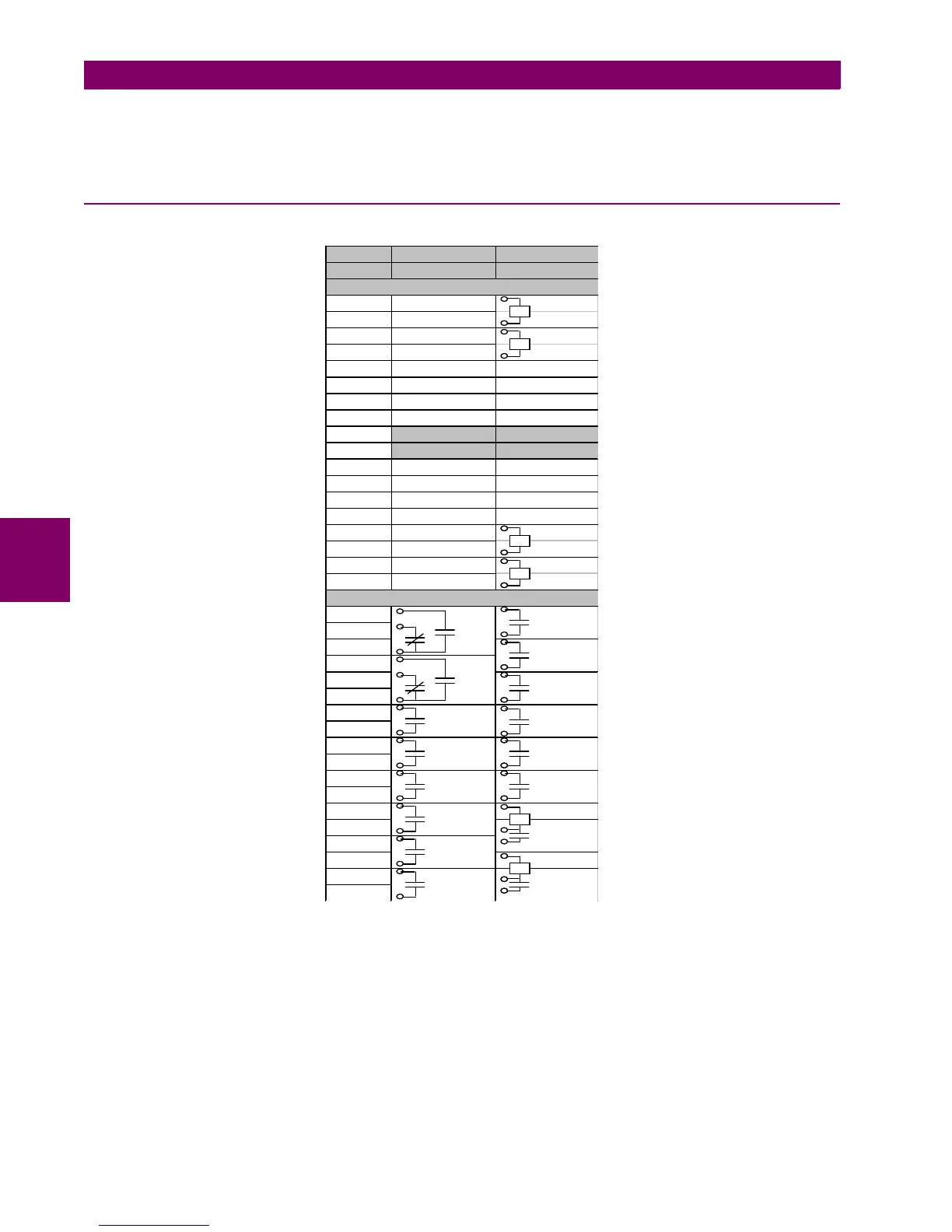
This section includes the Coil Supervision and mixed I/O boards, or any other board located on relay terminals F and G,
plus H and J connectors from the remote Bus Can I/O modules (CIO)
5.6.1 INPUT/OUTPUT PLACEMENT
.
Figure 5–28: INPUT/OUTPUT LOCATION AND TYPE
M IXED SUPERVISIO N
TERM INA L
12
1CC1 CO IL 1
2CC2 52/a
3CC3 CO IL 1
4CC4 52/b
5 CC5 CC1
6 CC6 CC2
7 CC7 CC3
8 CC8 CC4
9 CO M M O N 1/8 CO M M O N 1/4
10 C O M M O N 9/16 C O M M O N 5/8
11 CC9 CC5
12 CC10 CC6
13 CC11 CC7
14 CC12 CC8
15 C C 13 CO IL 2
16 C C 14 52/a
17 C C 15 CO IL 2
18 C C 16 52/b
19
20
21
22
23
24
25
26
27
28
29
30
31 I SENS
32
33
34 I SENS
35
36
O1
O6
O7
O8
O2
O3
O4
O5
OUTPUTS
IN P U T S
O8
O7
O1
O2
O3
O4
O5
O6
VVV VVVIII

 Loading...


