GE Multilin F650 Digital Bay Controller 5-113
5 SETPOINTS 5.6 INPUTS/OUTPUTS
5
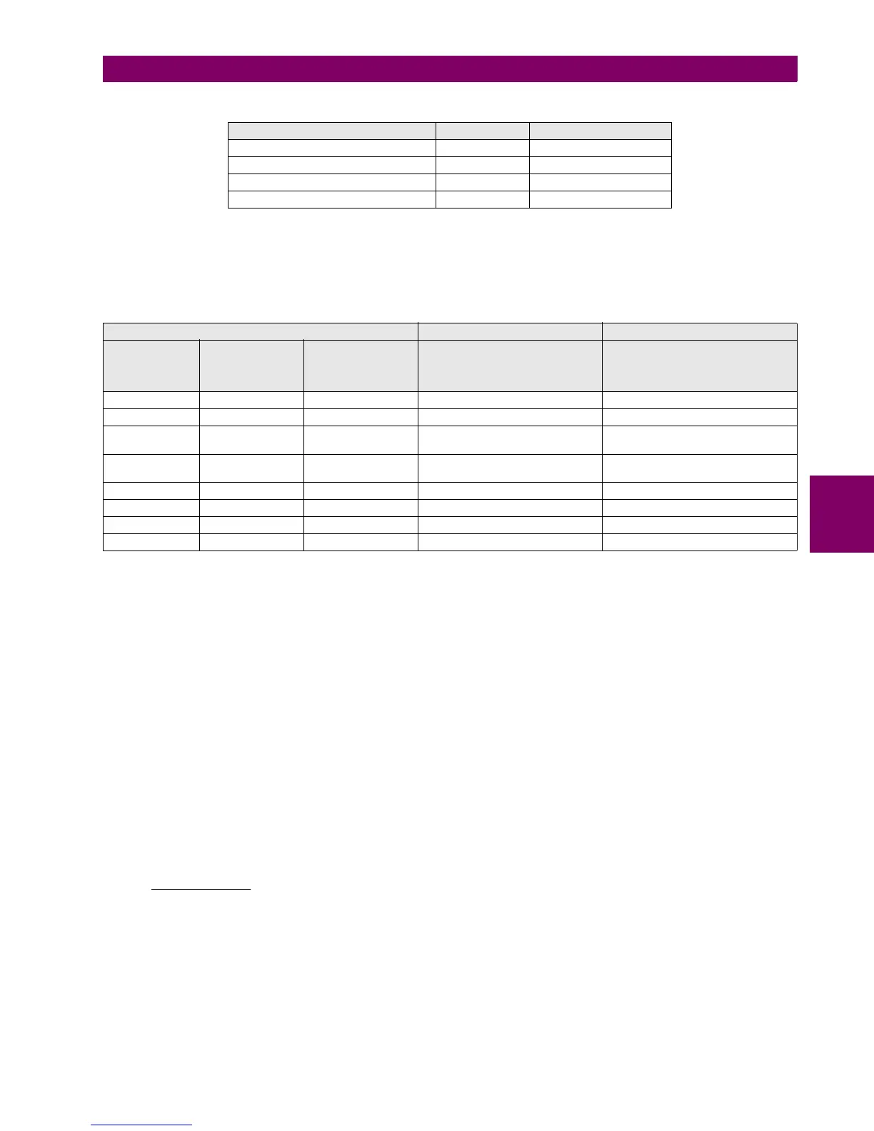
Table 5–90: SUPERVISION WITH 52/A
There is a possibility to monitor the trip circuit and trip coil continuity. This can be done by monitoring Vdc through the
output contact when this is open.
Table 5–91: SUPERVISION ALGORITHM WITH SIMPLE VOLTAGE SUPERVISION SCHEME
In this table, ON means that the voltage detector V52/a is active, detecting voltage presence.
In the first case shown on the table, with closed breaker, voltage is detected by V 52/a sensor, and this means that there is
continuity in the supervised circuit.
As shown on , when the relay is not tripped, trip contact F35-F36 remains open. If the breaker is closed, its auxiliary contact
52a is closed. Therefore, a little current is flowing, about 2 mA, through terminals F15 and F16 through the voltage detector
circuit, which flows through 52/a and the tripping coil 52TC (TC = tripping coil). Current will only circulate when there is
continuity in the whole circuit, so the complete circuit is monitored, and not only the trip coil. This circuit includes auxiliary
52/a as well as the whole wiring between the battery and the relay tripping terminals, and between these and the breaker
tripping circuit.
For the second case shown on the table, open breaker, its auxiliary contact 52/a remains open, and current
cannot flow through it for detecting continuity. In order to correctly monitor the circuit, a resistor must be used,
not included in the protection, connected in parallel. The value of resistance will be selected so that the V 52/a
input circuit minimum detection current flows, but not as high as to activate the breaker-tripping coil. The figure
shows the following equation:
Where:
Vmin Is the minimum voltage, in Volts, expected in the battery (e.g. 80% of Vn)
R Resistance, in kilo ohms.
2 2 mA of approximate current flowing through input V 52/a
As shown in the second case in the table, with an open breaker, as current will flow through R if there is continuity in the
WHOLE tripping circuit, voltage will be detected in input V 52/a.
INTERNAL STATE V 52/A SUPERVISION
52 open ON Ok
52 closed ON Ok
TRIP OFF Ok if t < 0.5 s
TRIP with 52 open OFF Ok if t < 0.5 s
STATUS OF INVOLVED ELEMENTS INPUT TO F650 DECISION
CIRCUIT
STATUS
OUTPUT
STATUS
(F35-F36)
BREAKER
STATUS
OPERAND
CONT IP_X_CC11
(VA_COIL2)
V 52/A (F15-F16)
OPERAND
CONT IP_X_CC16
(SUP_COIL2)
Healthy Open 52 closed ON ON
Healthy Open 52 open ON ON
Healthy Closed 52 closed OFF ON (if t < 500 ms)
OFF (if t > 500 ms)
Healthy Closed 52 open OFF ON (if t < 500 ms)
OFF (if t > 500 ms)
Faulty Open 52 closed OFF OFF (500 ms delay)
Faulty Open 52 open OFF OFF (500 ms delay)
Faulty Closed 52 closed OFF OFF (500 ms delay)
Faulty Closed 52 open OFF OFF (500 ms delay)
2
15V
R
min

 Loading...


