5-120 F650 Digital Bay Controller GE Multilin
5.8 RELAY CONFIGURATION 5 SETPOINTS
5
5.8RELAY CONFIGURATION
Setpoint > Relay Configuration
This is the relay configuration section in which the relay can be configured (all input/output and LEDs configuration,
protection elements signals, graphic display configuration, etc) using internal states or already compiled equation on PLC
Editor (see section 5.9).
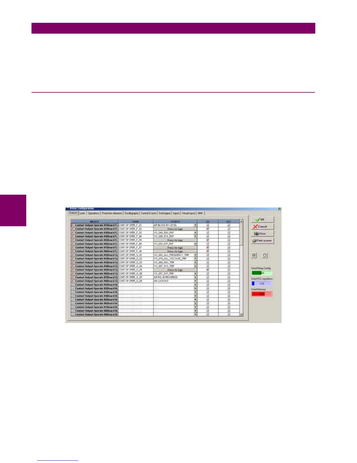
5.8.1 OUTPUTS
Configuration of contact output operates and reset signals for all boards available in the device:
To configure any output it is necessary to select the output to be configured, clicking on the checkbox in the select column
and choose the logic operand in the source column. Different simple logics can be performed in this screen, using the “or”
and “not” columns, for more complex logics go to the logic configuration tool to create the virtual outputs and afterwards
select it in the source column.
The different options available in this screen are the following:
• Select checkbox enables each output. The output must be enabled before modifying any other setpoint on that output
• Name setpoint for defining identification for the output.
• Source setpoint for defining a function, logic, remote input, digital input, etc. that will activate the contact.
• OR checkbox for configuring the output operation by activation of any of the indicated signals. The unit performs an
OR of the signals, and its output produces operation.
• NOT checkbox for inverting or not the configured logic.
Figure 5–40: OUTPUTS CONFIGURATION