5-38 F650 Digital Bay Controller GE Multilin
5.4 PROTECTION ELEMENTS 5 SETPOINTS
5
5.4.3 PHASE CURRENT
The F650 Phase current menu incorporates the following overcurrent elements:
Phase time overcurrent (51PH/51PL)
Phase instantaneous overcurrent (50PH/50PL)
Phase directional overcurrent (67P)
Thermal Model (49)
5.4.3.1 PHASE TIME DELAYED OVERCURRENT UNITS – PHASE TOC (51PH/51PL)
The phase overcurrent element (51P) operates in a time period that depends on the applied current and on the set curve.
The phase current input quantities may be programmed as fundamental phasor magnitude or total waveform RMS
magnitude as required by the application. The unit reset can be selected between Instantaneous and Linear (timed
according to the corresponding equation).
If the element timing is set as Definite Time, then the TD Multiplier setpoint will be use to define both the Operation time and
the Reset time of the unit, in case of selecting Linear reset.
The unit incorporates independent block inputs for each phase. When the unit is blocked, the tripping time counter is reset
to 0. This feature allows the use of this input to instantaneously reset the protection unit timing. The PICKUP setpoint of the
element can be dynamically reduced by a VOLTAGE RESTRAINT feature. The possible outputs for the protection element
logic are the pickup and tripping signals independent for each phase, and the general unit pickup and tripping signals.
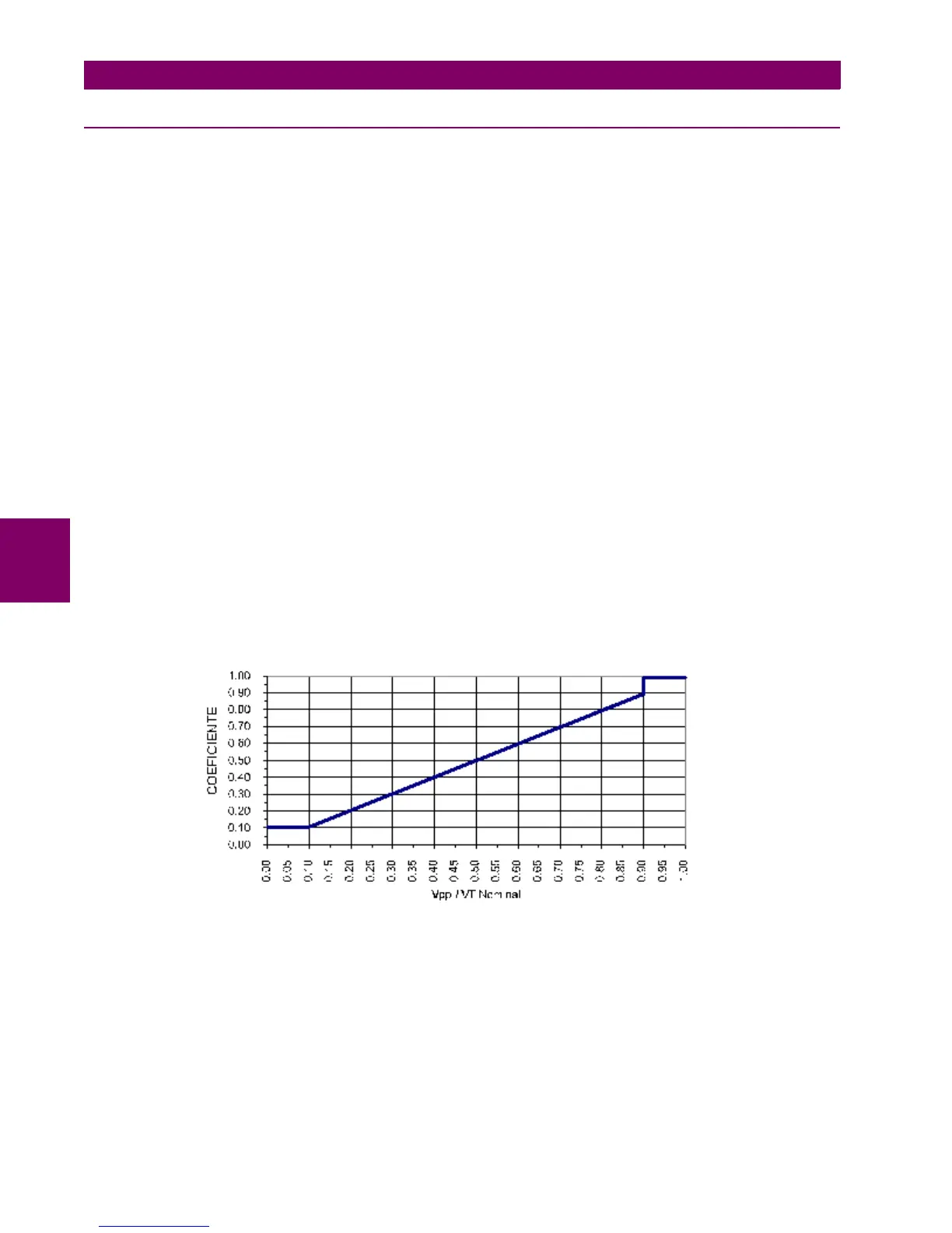
The pickup current magnitude can be dynamically reduced depending on the existing voltage value, using the Voltage
Restraint setpoint. The pickup current level is proportional to the phase-to-phase voltage measured according to a
coefficient shown on Figure 5–4: .This is accomplished via the multipliers (Mvr) corresponding to the phase-phase voltages
of the voltage restraint characteristic curve; the pickup level is calculated as ‘Mvr’ times the ‘Pickup’ setpoint. In the figure,
Vpp is the phase-to-phase voltage, and VT Nominal is the rated voltage set under General setpoints (please refer to section
1.3.1. BUSCAR REFERENCIA EN CAP. 1)
Figure 5–4: VOLTAGE RESTRAINT CHARACTERISTIC

 Loading...


