4-28 F650 Digital Bay Controller GE Multilin
4.1 ENERVISTA 650 SETUP SOFTWARE INTERFACE 4 HUMAN INTERFACES
4
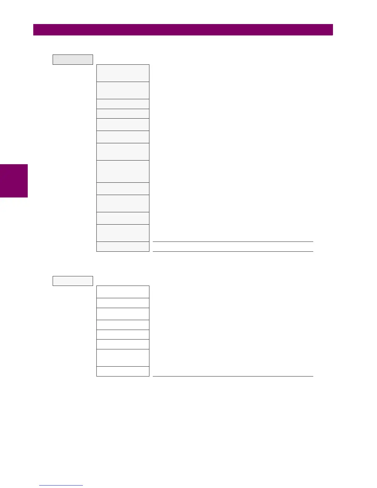
Table 4–17: GENERAL OVERVIEW OF STATUS MENU:
Table 4–18: DIFFERENT CONTROL ACTUAL VALUES INCLUDED IN THE CONTROL ELEMENTS MENU
STATUS
Operation bits
Up to 24 elements. OPERATION BIT XX is (0) when the configured time
out for the operation XX expires or when success conditions are met.
And it is (1) if operation XX is executed and interlocks are fulfilled.
Breaker
Breaker status (open, closed or undefined). The rest of the status signals
corresponding to the switchgear XX configured as breaker are in the
“Status>Switchgear Status>Switchgear XX” menu.
Protection Status of all the protection units in the device.
Control Elements Status of all the control units available in the device.
Protection Summary
This screen shows a complete list of all protection and control elements
in the relay, showing their status (enabled or not).
Snapshots events
summary
Summary of the snapshot events status (enabled or disabled) for
protection, control, inputs and outputs boards and switchgear.
ModBus User Map
Up to 256 elements. Value in SIGNED INT 16 BIT format of the reading
for the selected address configured in “Settings>Product
Setup>ModBus User Map”
Switchgear Status
Up to 16 blocks of switchgear status signals for the 16 configurable
devices. Status signals such as inputs for A and B contacts, status for A
and B, open and close status, error 00 and error 11, open init and close
init, fail to open and fail to close signals.
Calibration
Internal states for calibration. Factory calibration and calibration error
signals.
Flex Curves
Flex curve status for A, B, C and D user curves. (0) if it is not configured,
(1) if it is configured. To configure a flex curve go to “Settings>System
Setup>Flex Curves” menu.
System Info
This screen can monitor the system parameters and the internal status of
the Relay boot code. Not enabled by default, password required
Records Status
Information related to the different records stored in the Relay, such as:
Fault reports, control events, oscillography, data logger, demand, energy,
and breaker maintenance.
SNTP-IRIG-B Information related to synchronization via IRIG_B or SNTP
CONTROL
Frequency Status signals (pickups and operations) for under and overfrequency
units.
Synchrocheck Status signals for synchrocheck function (25).
Autoreclose Status signals for autoreclose function (79). Close signal, recloser status
(ready, lockout, etc), block signals after each shot.
Breaker Failure Status signals for breaker failure function (50BF).
VT Fuse Failure Fuse failure detection signal.
Broken Conductor Status signals (pickups and operations) for broken conductor (I2/I1).
Setting Groups Status signals (activations and blocks) for the relay setting group change.
By default the “setting group” setting is disabled and all the grouped
elements can be enabled at the same time.
Locked Rotor Status signals (pickups and operations) for locked rotor units.

 Loading...


