5-80 F650 Digital Bay Controller GE Multilin
5.5 CONTROL ELEMENTS 5 SETPOINTS
5
5.5.4.1 VOLTAGE INPUTS
In order to perform the synchronism check function, the F650 uses only one voltage from each end of the breaker. Voltage
values to be compared must be on the same basis, either phase-to-phase or phase-to-ground voltage; they must be the
same at both ends of the breaker; it is not possible to compare a phase-to-ground voltage at one end with a phase-to-
phase voltage at the other end.
Additionally, if on one end, three voltages have been connected, the necessary voltage on the other end for Function 25 will
only be single-phase voltage. If there is only one voltage (either phase-to-phase or phase-to-ground) at both ends of the
breaker, this must be from the same phase in both cases.
The selection of voltage values to be used by the synchronism unit is made in the relay General setpoints:
V1 is the line voltage, selectable from the relay voltage channels, using the “Frequency Reference” setpoint at
Setpoint > System Setup > General setpoints > Frequency Reference. (Please refer to the voltage
correspondence )
V2 is the busbar voltage measured at the auxiliary voltage input (terminals A11-A12). To enable the busbar voltage
metering in the relay, it is required to select VX in the Auxiliary Voltage setpoint at Setpoint > System Setup >
General setpoints > Auxiliary Voltage.
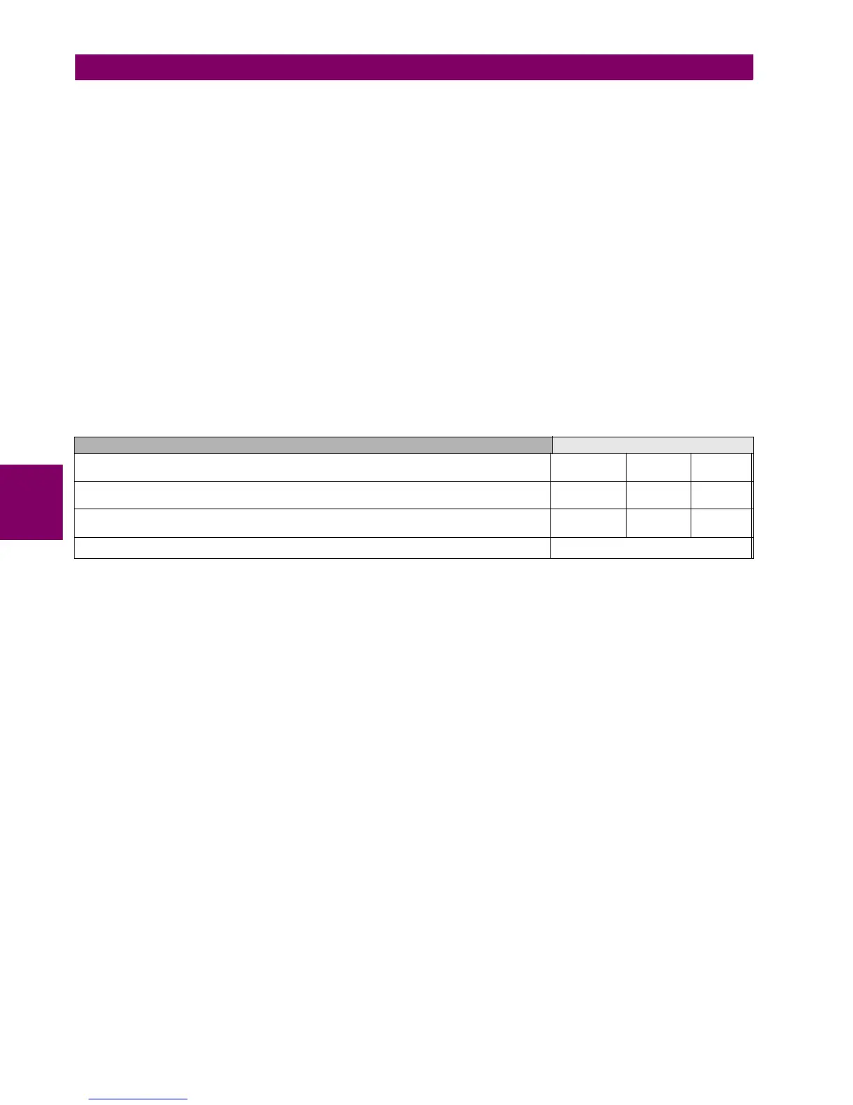
The voltage correspondence is detailed in the following table:
Table 5–71: VOLTAGE CORRESPONDENCE UNIT 25
setpoints/System Setup/General setpoints/Auxiliary Voltage setpoint must be set to Vx, in order to monitor auxiliary
voltage instead of Vn (neutral voltage, coming from an open delta connection).
5.5.4.2 APPLICATION
Even if the application range of F650 is quite wide and the unit can be used in distribution lines at any voltage level, it must
be taken into account that it is a three-pole tripping relay, designed for managing a single breaker. This is why F650 is
not suitable for one and a half breaker configurations, or ring configurations where a transmission line or feeder has two
breakers.
VOLTAGE CORRESPONDENCE
setpoints>System Setup>General setpoints>Frequency Reference
Voltage selection for unit 25 of F650
V
I
V
II
V
III
setpoints>System Setup>General setpoints>Phase VT Connection=WYE
Phase-to-ground voltage connection.(Wye connection)
V
a-g
V
b-g
V
c-g
setpoints>System Setup>General setpoints>Phase VT Connection=DELTA Phase-to-
phase voltage connection.(Delta connection).
V
a-b
V
b-c
V
c-a
setpoints>System Setup>General setpoints> Auxiliary Voltage=VX V
x

 Loading...


