GE Multilin F650 Digital Bay Controller 5-101
5 SETPOINTS 5.5 CONTROL ELEMENTS
5
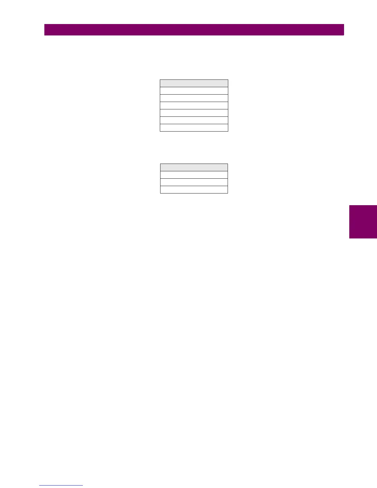
The signals related to the locked rotor pickups and operations for the three locked rotor units can be viewed at Actual >
Status > Control Elements > Locked Rotor and they are as follows:
Table 5–83: LOCKED ROTOR STATUS
The block signals for the locked rotor unit can be configured at: Setpoint > Relay Configuration > Protection Elements
Table 5–84: LOCKED ROTOR BLOCKS
Note:
The unit works with primary values.
The unit will pickup if at least one of the three phase currents are above the adjusted level. The operation value will be the
higher of the three.
Reset level at 97% of the pickup level.
LOCKED ROTOR STATUS
LOCKED ROTOR1 PKP
LOCKED ROTOR1 OP
LOCKED ROTOR2 PKP
LOCKED ROTOR2 OP
LOCKED ROTOR3 PKP
LOCKED ROTOR3 OP
LOCKED ROTOR BLOCKS
LOCKED ROTOR1 BLK
LOCKED ROTOR2 BLK
LOCKED ROTOR3 BLK

 Loading...


