5-54 F650 Digital Bay Controller GE Multilin
5.4 PROTECTION ELEMENTS 5 SETPOINTS
5
b) CURRENT POLARIZATION OPERATION PRINCIPLES:
Operation Magnitude
: In = 3·Io, calculated from the phase currents.
Polarization Magnitude: Ip, measured at input terminals B11-B12.
To perform a directional comparison by current, the polarization magnitude used is the current measured at the relay Ip
input, terminals B11-B12, with input or “positive” in B11. This current is taken from the source (transformer or generator)
neutral grounding.
Direction is considered to be forward when the phase shift between both magnitudes is lower than 85º. If the angle is higher
than 85º, the fault is considered to be reverse.
The following table shows the unit output signals management (block and permission) depending on the polarization type
setpoint.
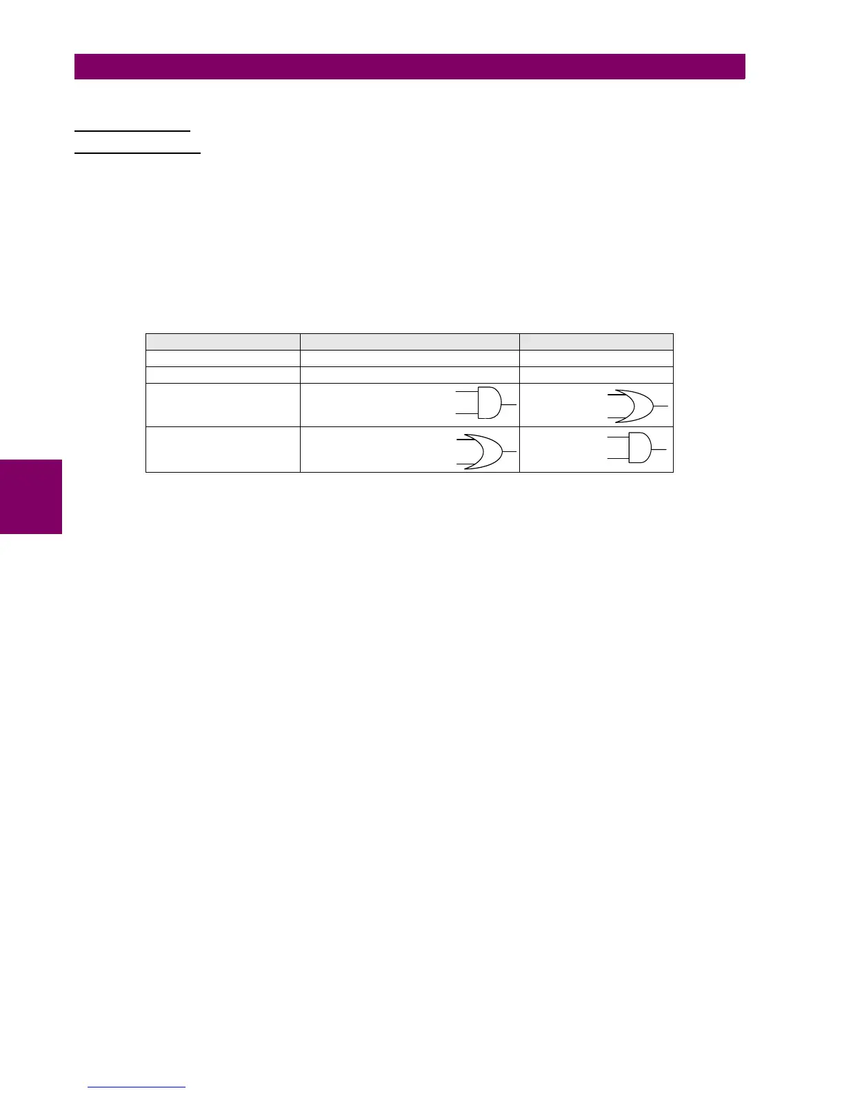
Table 5–47: OUTPUT SIGNALS MANAGEMENT ACCORDING TO THE POLARIZATION TYPE SETPOINT
Configuration of the required signals for blocking the neutral overcurrent units from the signals provided by the neutral
directional units is performed at Setpoint > Relay Configuration > Protection Elements using the inverted operation
signals to block the trip, as shown in the following example:
How to block neutral time overcurrent units with neutral directional functions:
NEUTRAL TOC1 BLOCK = NOT (NEUTRAL DIR1 OP)
NEUTRAL TOC2 BLOCK = NOT (NEUTRAL DIR2 OP)
NEUTRAL TOC3 BLOCK = NOT (NEUTRAL DIR3 OP)
To block neutral instantaneous units:
NEUTRAL IOC1 BLOCK = NOT (NEUTRAL DIR1 OP)
NEUTRAL IOC2 BLOCK = NOT (NEUTRAL DIR2 OP)
NEUTRAL IOC3 BLOCK = NOT (NEUTRAL DIR3 OP)
POLARIZATION SETPOINT NEUTRAL DIR BLOCK SIGNAL NEUTRAL DIR OP SIGNAL
Vo Vo < POL V THRESHOLD setpoint Permission Vo
Ip Ip < 5 mA Permission Ip
Vo + Ip Vo < POL V THRESHOLD
Ip < 5 Ma
Permission Vo
Permission Ip
Vo * Ip Vo < POL V THRESHOLD
Ip < 5 mA
Permission Vo
Permission Ip

 Loading...


