5-132 F650 Digital Bay Controller GE Multilin
5.8 RELAY CONFIGURATION 5 SETPOINTS
5
On the left side of the window all the available elements to be programmed on the HMI are displayed. Their meaning is
detailed on the right.
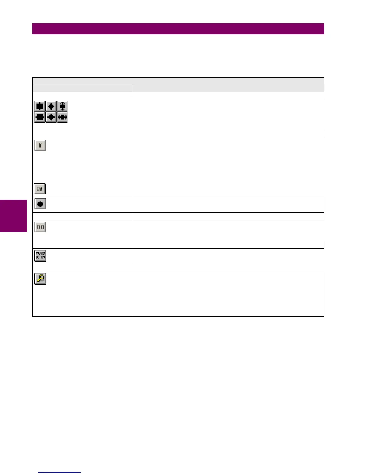
Table 5–96: ACTIVE SYMBOLS CONFIGURABLE IN ONE-LINE DIAGRAM FOR GRAPHICAL HMI
ACTIVE SYMBOLS
ICONS IN SCREEN DESCRIPTION
SWITCHGEAR SYMBOLS
These symbols correspond to switchgear elements: breaker (square) and selector switch
(rhombus), in vertical and horizontal positions. It is necessary to associate the figure to its
corresponding switchgear number. The figure is shown filled if the element is closed, and
blank if the element is open. The symbol on the right represents an unpluggable breaker.
In this case it is necessary to indicate which operands show whether the element is
plugged or unplugged. The figure shows also graphically these two statuses.
MULTISTATE VARIABLE SYMBOL
Displays on screen a dialog box that is one variable status function (like a switch case) for
the following internal states AR STATUS, AR LOCKOUT MODE, AR BLOCK MODE and
FAULT TYPE.
This type of data allows to visualize the different states of one particular value, for
example, AR STATUS has several states such as (0) OUT OF SERVICE, (1) READY, (2)
LOCKOUT, (3) BLOCK, (4) RECLOSE IN PROGRESS. Significant texts can be
associated with those states.
STATUS SYMBOLS (TEXT AND GRAPHIC MODES):
BitRepresents the state of an operand by means of a configurable text. It allows
associating a test to the active status and a different text to the inactive status.
Led(O)Performs the same function in a graphical mode. This way, it works as a virtual
LED. When showing a black circle, it means that the selected operand is active, and if the
circle is blank, the operand is inactive
ANALOG MAGNITUDE SYMBOL
Used for displaying analog magnitudes (current, voltage, power, etc.) in floating point
numbers, such as a current value (123.5 A). Both the number of decimals and the integer
characters can be selected, in order to facilitate the reading. Any of the analog
magnitudes available in the relay can be configured
DATE AND TIME SYMBOL
Symbol used for displaying in the HMI the date and time provided by the device.
OPERATIONS SYMBOL:
This symbol indicates de possibility to configure and execute operations on the graphic
display. This symbol can only be selected once the operations have already been
configured in the “Operations” screen of the “Relay Configuration” menu. To select an
Operation, click on the element and then on the display. The program will show a window
to select the required operation among the displayed options, and the tab order. Once
selected, a red border square will be shown. Place this square on the object to be
operated. When the operated object is selected on the screen to execute this operation,
the object on which it is located will blink. It is possible to place several operations on the
same object, for example to open and close the breaker object.

 Loading...


