GE Multilin F650 Digital Bay Controller 6-3
6 ACTUAL VALUES 6.2 STATUS
6
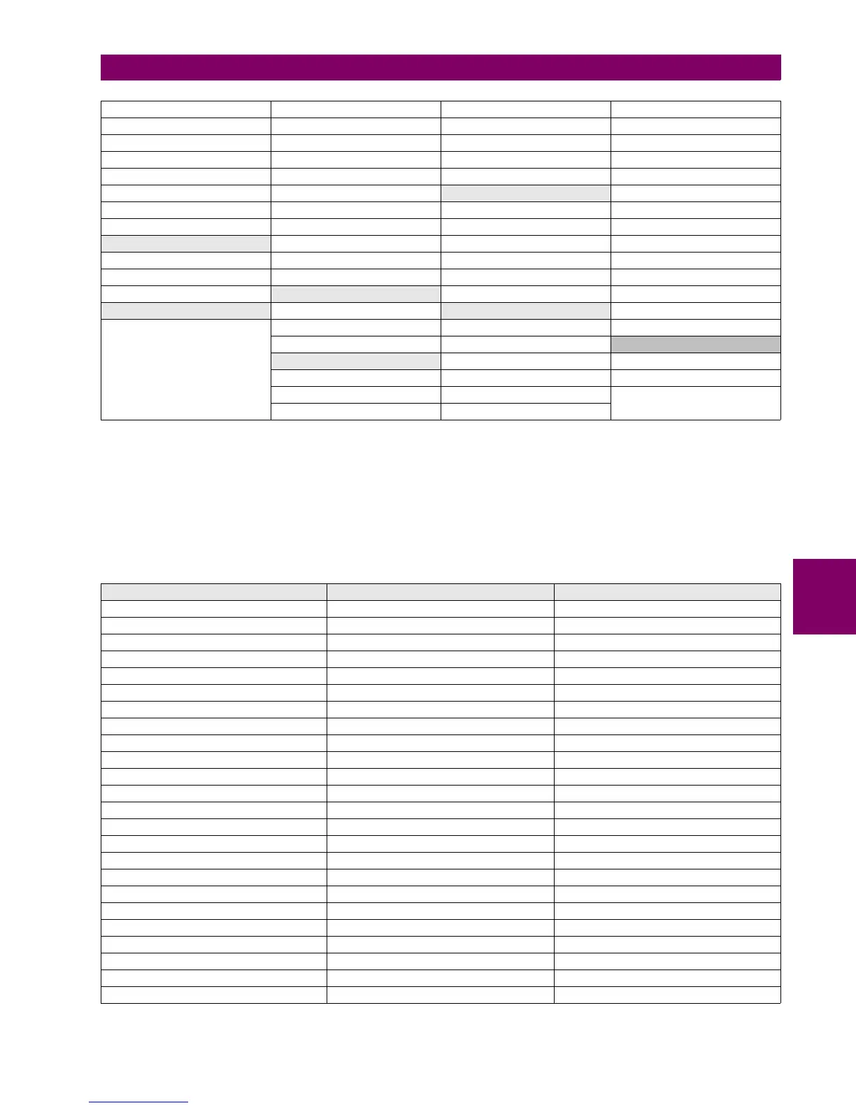
6.2.3.2 PHASE CURRENT
This screen shows the pickup and trip for all phase instantaneous and time overcurrent elements in the F650 and block and
operation signals provided by the phase directional units. Any of these two events of any phase element will light up the
corresponding LED in this screen, and it will remain lit as the associated function remains in pickup or operation. All the
values are provided for phases and total as shown on the table below.
This screen is accessed in menu: Actual> Status > Protection > Phase Current, and includes the following signaling
LEDs:
Table 6–5: PHASE CURRENT ACTUAL VALUES
NEUTRAL IOC2 BLOCK NEUTRAL TOC2 BLOCK GROUND DIR2 BLK INP NEUTRAL OV2 HIGH BLK
NEUTRAL IOC3 BLOCK NEUTRAL TOC3 BLOCK GROUND DIR3 BLK INP NEUTRAL OV3 HIGH BLK
GROUND IOC1 BLOCK GROUND TOC1 BLOCK SENS GND DIR1 BLK IP NEUTRAL OV1 LOW BLK
GROUND IOC2 BLOCK GROUND TOC2 BLOCK SENS GND DIR2 BLK IP NEUTRAL OV2 LOW BLK
GROUND IOC3 BLOCK GROUND TOC3 BLOCK SENS GND DIR3 BLK IP NEUTRAL OV3 LOW BLK
SENS GND IOC1 BLK SENS GND TOC1 BLOCK
POWER BLOCKS AUXILIARY UV1 BLOCK
SENS GND IOC2 BLK SENS GND TOC2 BLOCK FWD PWR1 BLOCK AUXILIARY UV2 BLOCK
SENS GND IOC3 BLK SENS GND TOC3 BLOCK FWD PWR2 BLOCK AUXILIARY UV3 BLOCK
ISOLATED GROUND BLOCKS NEG SEQ TOC1 BLOCK FWD PWR3 BLOCK AUXILIARY OV1 BLOCK
ISOLATED GND1 BLK NEG SEQ TOC2 BLOCK DIR PWR1 BLOCK AUXILIARY OV2 BLOCK
ISOLATED GND2 BLK NEG SEQ TOC3 BLOCK DIR PWR2 BLOCK AUXILIARY OV3 BLOCK
ISOLATED GND3 BLK
THERMAL MODEL BLOCKS DIR PWR3 BLOCK NEG SEQ OV1 BLOCK
SETTING GROUPS BLOCK IP THERMAL1 BLOCK FREQUENCY BLOCKS NEG SEQ OV2 BLOCK
SETT GROUPS BLOCK THERMAL2 BLOCK OVERFREQ1 BLOCK NEG SEQ OV3 BLOCK
THERMAL3 BLOCK OVERFREQ2 BLOCK
LOCKED ROTOR BLK
BROKEN CONDUCTOR BLK OVERFREQ3 BLOCK LOCKED ROTOR1 BLK
BROKEN CONDUCT1 BLK UNDERFREQ1 BLOCK LOCKED ROTOR2 BLK
BROKEN CONDUCT2 BLK UNDERFREQ2 BLOCK LOCKED ROTOR3 BLK
BROKEN CONDUCT3 BLK UNDERFREQ3 BLOCK
PHASE IOC ACTUAL VALUES PHASE IOC ACTUAL VALUES PHASE DIRECTIONAL ACTUAL VALUES
PH IOC1 HIGH A / B / C PKP PH TOC1 HIGH A / B / C PKP PHASE DIR1 BLOCK A
PH IOC1 HIGH A / B / C OP PH TOC1 HIGH A / B / C OP PHASE DIR1 A OP
PH IOC1 HIGH PKP PH TOC1 HIGH PKP PHASE DIR1 BLOCK B
PH IOC1 HIGH OP PH TOC1 HIGH OP PHASE DIR1 B OP
PH IOC2 HIGH A / B / C PKP PH TOC2 HIGH A / B / C PKP PHASE DIR1 BLOCK C
PH IOC2 HIGH A / B / C OP PH TOC2 HIGH A / B / C OP PHASE DIR1 C OP
PH IOC2 HIGH PKP PH TOC2 HIGH PKP PHASE DIR2 BLOCK A
PH IOC2 HIGH OP PH TOC2 HIGH OP PHASE DIR2 A OP
PH IOC3 HIGH A / B / C PKP PH TOC3 HIGH A / B / C PKP PHASE DIR2 BLOCK B
PH IOC3 HIGH A / B / C OP PH TOC3 HIGH A / B / C OP PHASE DIR2 B OP
PH IOC3 HIGH PKP PH TOC3 HIGH PKP PHASE DIR2 BLOCK C
PH IOC3 HIGH OP PH TOC3 HIGH OP PHASE DIR2 C OP
PH IOC1 LOW A / B / C PKP PH TOC1 LOW A / B / C PKP PHASE DIR3 BLOCK A
PH IOC1 LOW A / B / C OP PH TOC1 LOW A / B / C OP PHASE DIR3 A OP
PH IOC1 LOW PKP PH TOC1 LOW PKP PHASE DIR3 BLOCK B
PH IOC1 LOW OP PH TOC1 LOW OP PHASE DIR3 B OP
PH IOC2 LOW A / B / C PKP PH TOC2 LOW A / B / C PKP PHASE DIR3 BLOCK C
PH IOC2 LOW A / B / C OP PH TOC2 LOW A / B / C OP PHASE DIR3 C OP
PH IOC2 LOW PKP PH TOC2 LOW PKP
PH IOC2 LOW OP PH TOC2 LOW OP
PH IOC3 LOW A / B / C PKP PH TOC3 LOW A / B / C PKP
PH IOC3 LOW A / B / C OP PH TOC3 LOW A / B / C OP
PH IOC3 LOW PKP PH TOC3 LOW PKP
PH IOC3 LOW OP PH TOC3 LOW OP

 Loading...


