6-12 F650 Digital Bay Controller GE Multilin
6.2 STATUS 6 ACTUAL VALUES
6
6.2.4.7 SETTING GROUPS
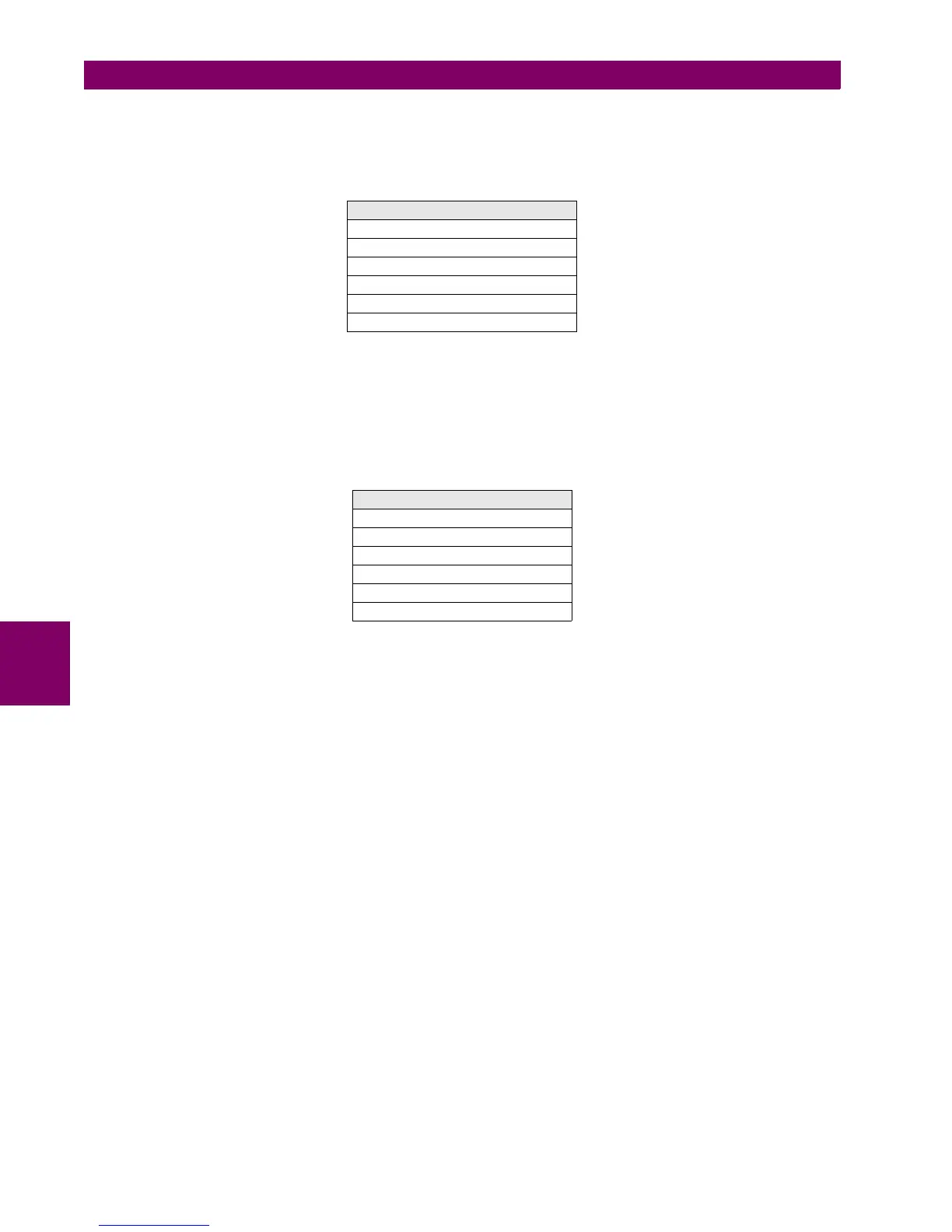
This screen can be accessed at Actual> Status > Control Elements > Setting Groups, and it includes activation and
block signals for the relay setting groups change in the following signaling LEDs:
Table 6–19: SETTING GROUP ACTUAL VALUES
6.2.4.8 LOCKED ROTOR
F650 units incorporate three locked rotor units. For each of them there are two magnitudes pickup and trip (operation).
This screen shows the activation of all locked rotor elements available in the F650. It can be accessed from the menu:
Actual> Status > Control Elements > Locked Rotor, and it includes the following signaling LEDs.
Table 6–20: LOCKED ROTOR ACTUAL VALUES
SETTING GROUPS ACTUAL VALUES
GROUP 1 ACT ON
GROUP 2 ACT ON
GROUP 3 ACT ON
GROUP 1 BLOCKED
GROUP 2 BLOCKED
GROUP 3 BLOCKED
LOCKED ROTOR ACTUAL VALUES
LOCKED ROTOR1 PKP
LOCKED ROTOR1 OP
LOCKED ROTOR2 PKP
LOCKED ROTOR2 OP
LOCKED ROTOR3 PKP
LOCKED ROTOR3 OP

 Loading...


