GE Multilin F650 Digital Bay Controller 3-11
3 HARDWARE 3.3 WIRING
3
3.3.3 CABLE/FIBER ETHERNET BOARD
The Ethernet board is the communication board 2 (COM3) shown in Figure 3–2:: COMMUNICATIONS
MODULE. It is located in the bottom at the rear part of the relay.
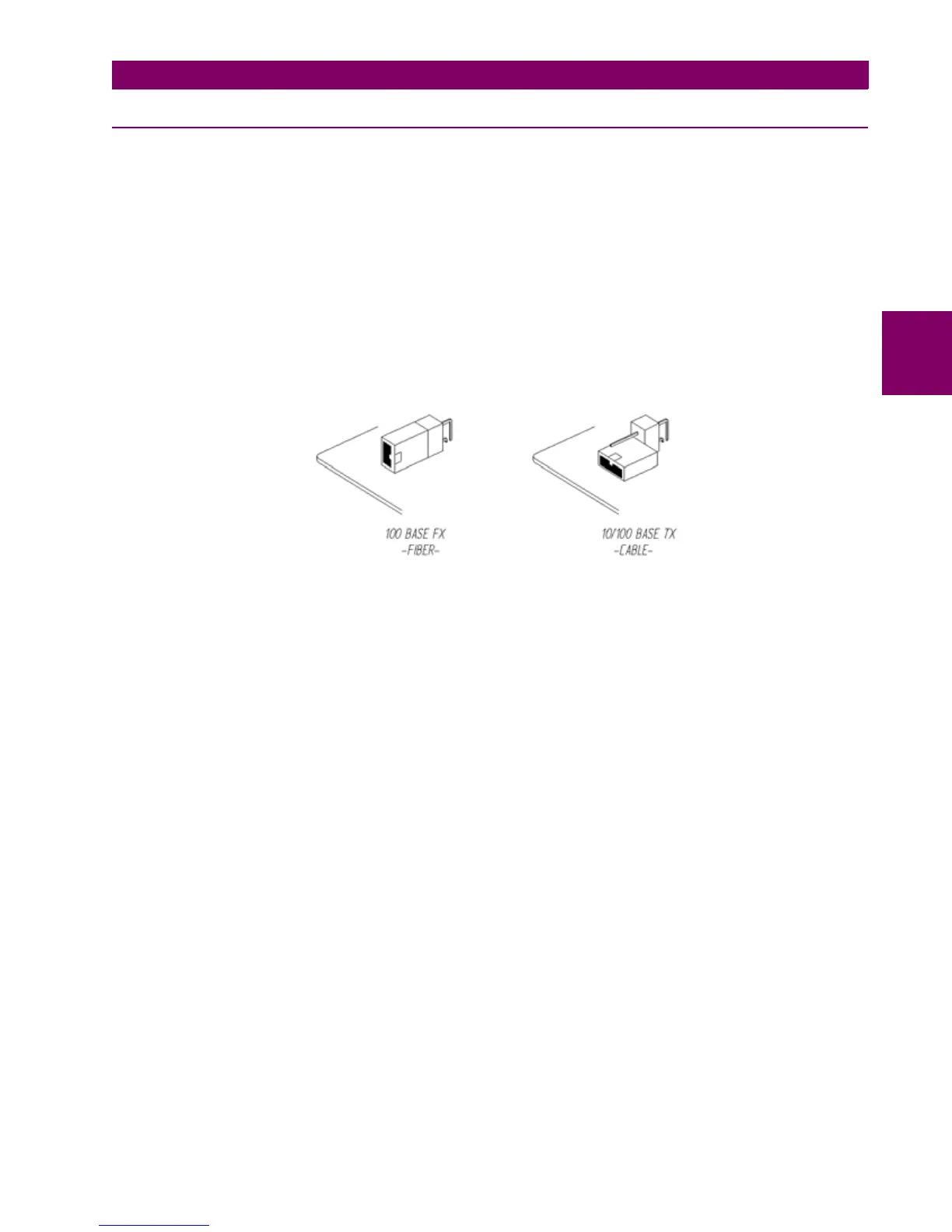
In Models C and D, the 10/100BaseTX port is selected by an internal switch. To select between fiber and cable
it is necessary to extract the board, switch the jumper to the selected position, as indicated on Figure 3–10::
FIBER/CABLE SELECTION and insert the board again. As with any other relay manipulation, the relay power
supply must be removed and the operation must be performed only by skilled personnel.
The default port selected by switch is 10/100 TX in factory configuration. The switch selects between cable
(10/100 TX) and the first fiber port (100 FX). In Ethernet board type D (double fiber port) the backup channel is
always fiber.
Figure 3–10: FIBER/CABLE SELECTION

 Loading...


