GE Multilin F650 Digital Bay Controller C-11
APPENDIX C C.1 DNP 3.0 PROTOCOL FOR F650
C
C.1.5 DNP CONFIGURATION EXAMPLES
C.1.5.1 CONFIGURING DNP USER MAP
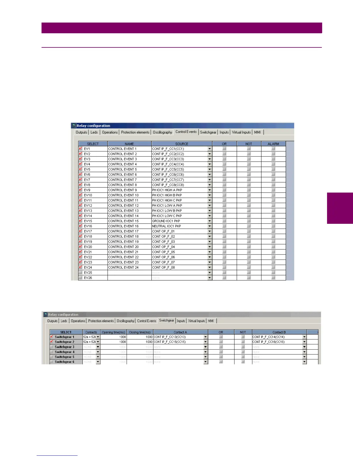
Imagine that a user wants to configure DNP Binary Inputs Map with 8 Contact Inputs, 8 Protection states, 8 Contact
Outputs and 2 Switchgears. This configuration can be done in two steps. In first step the user selects “Setpoint->Relay
Configuration” from the F650PC program and then configures Control Events bits and Switchgear bits. It is shown in figures
9.1 and 9.2. In the second step the user selects “Setpoint->System Setup->Communication settings->DNP” in order to
change DNP Binary Input Block settings. The user set values of the first three Binary Input blocks, Binary Input Block1 =
CTL EVENTS 1-16, Binary Input Block2 = CTL EVENTS 17-32, Binary Input Block3 = SWITCHGEAR 1-8. It is shown in
Configuration of Control Events bits
Figure C–1: CONFIGURATION OF CONTROL EVENTS BITS
Figure C–2: CONFIGURATION OF SWITCHGEAR

 Loading...


