GE Multilin F650 Digital Bay Controller 5-39
5 SETPOINTS 5.4 PROTECTION ELEMENTS
5
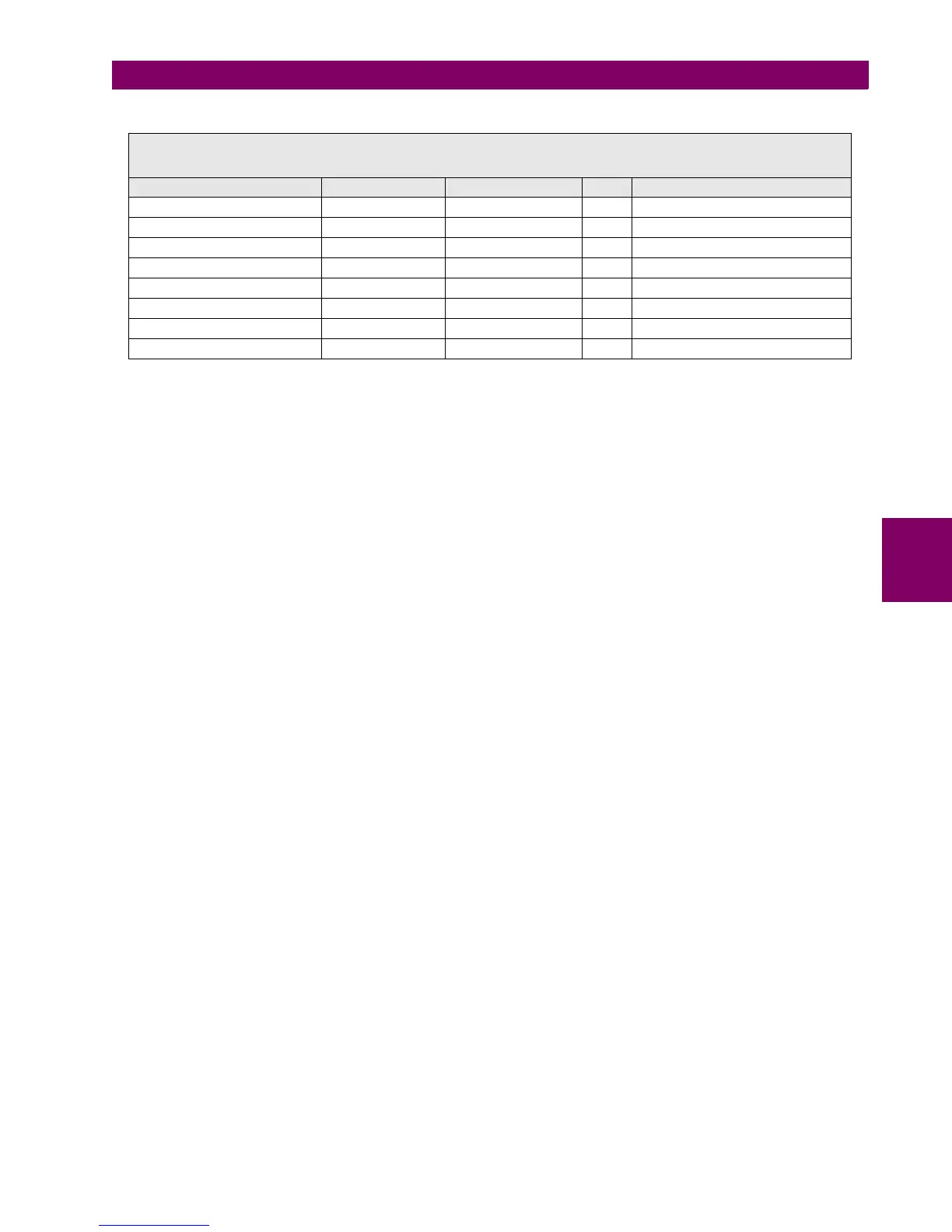
Table 5–38: 51PH/51PL UNIT SETPOINTS
If the voltage restraint feature is disabled, the pickup level always remains at the value set in the Pickup Level setpoint.
The snapshot event setpoint enables or disables the snapshot event generation for the phase time overcurrent units.
SETPOINT > PROTECTION ELEMENTS > PHASE CURRENT >
> PHASE TOC HIGH > PHASE TOC HIGH 1> PHASE TOC HIGH 2 > PHASE TOC HIGH 3
> PHASE TOC LOW > PHASE TOC LOW 1 > PHASE TOC LOW 2 > PHASE TOC LOW 3
SETPOINT DESCRIPTION NAME DEFAULT VALUE STEP RANGE
Function permission Function DISABLED N/A [DISABLED – ENABLED]
Input type Input PHASOR(DFT) N/A [PHASOR – RMS]
Pickup level Pickup Level 1.00 0.01 A [0.05 : 160.00]
Curve shape Curve IEEE Ext Inv N/A [See list of curves]
Time Dial TD Multiplier 1.00 0.01 s [0.00 : 900.00]
Reset type Reset INSTANTANEOUS N/A [INSTANTANEOUS – LINEAR]
Voltage Restraint Voltage Restraint DISABLED N/A [DISABLED – ENABLED]
Snapshot Event generation Snapshot Events ENABLED N/A [DISABLED – ENABLED]

 Loading...


