GE Multilin F650 Digital Bay Controller 9-7
9 COMMISSIONING 9.7 VERIFICATION OF MEASURE
9
9.7VERIFICATION OF MEASURE
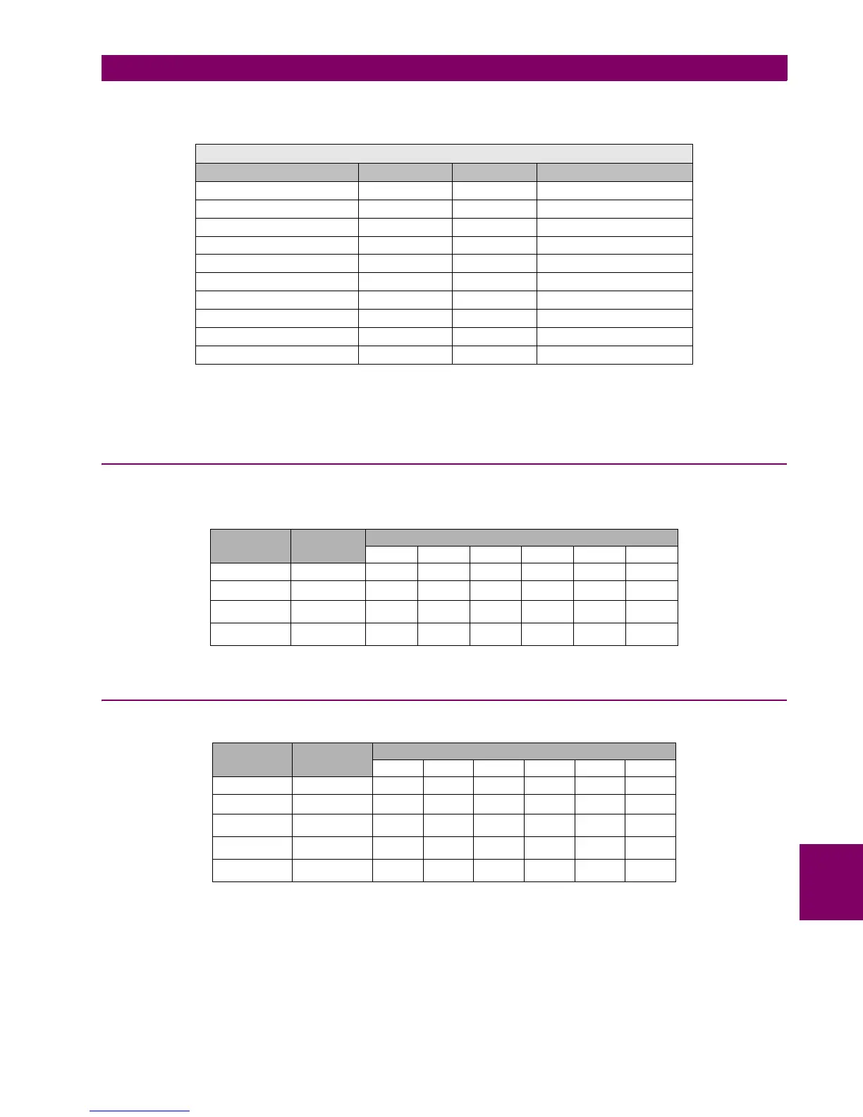
Set the relay as follows
NOTE:
ALL ANGLES INDICATED ARE DELAY ANGLES
ALL VALUES OBTAINED IN THIS TEST MUST BE THE ONES CORRESPONDING TO THE DFT
9.7.1 VOLTAGES
Apply the following current and frequency values to the relay:
Verify that the relay measures the values with an error of +/-1 % of the applied value plus 0,1% of full scale (275V).
9.7.2 PHASE CURRENTS
Apply the following voltage and frequency values to the relay:
Verify that the relay measures the values with an error lower than +/-0.5% of the test value or+/- 10 mA, whichever is
greater, for phases and ground.
Verify that the relay measures the values with an error lower than +/-1.5% of the test value or+/- 1 mA, whichever is greater,
for sensitive ground (SG).
GENERAL SETTINGS
NAME VALUE UNITS RANGE
PHASE CT RATIO 1.0 0.1 1.0-6000.0
GROUND CT RATIO 1.0 0.1 1.0-6000.0
STV GROUND CT RATIO 1.0 0.1 1.0-6000.0
PHASE VT RATIO 1.0 0.1 1.0-6000.0
PHASE VT CONNECTION WYE N/A WYE – DELTA
NOMINAL VOLTAGE 100 V 0.1 1-250 V
NOMINAL FREQUENCY 50 Hz 1 Hz 50-60 Hz
PHASE ROTATION ABC N/A ABC – ACB
FREQUENCY REFERENCE VI N/A VI-VII-VIII
AUXILIARY VOLTAGE VX N/A VX – VN
CHANNEL ANGLE FREQUENCY
50 Hz 60 Hz 50 Hz 60 Hz 50 Hz 60 Hz
VI 0º 0 5 50 100 150 275
VII 120º 0 5 50 100 150 275
VIII 240º 0 5 50 100 150 275
VX 0º 0 5 50 100 150 275
CHANNEL ANGLE FREQUENCY
50 Hz 60 Hz 50 Hz 60 Hz 50 Hz 60 Hz
Ia (A) 45º 01510510.1
Ib (A) 165º 0 15 10 5 1 0.1
Ic (A) 285º 0 15 10 5 1 0.1
IG(A) 0º 0 15 10 5 1 0.1
ISG(A) 0º 0 5 1 0.1 0.01 0.005

 Loading...


