GE Multilin F650 Digital Bay Controller 9-21
9 COMMISSIONING 9.15 FREQUENCY ELEMENTS (81O/81U)
9
9.15FREQUENCY ELEMENTS (81O/81U)
Set the relay to trip for the protection element being tested. Configure any of the outputs to be activated only by the
protection element being tested.
Set the relay as follows:
Apply voltage as indicated on the table, modifying frequency from the maximum threshold (48 Hz) to the minimum (46 Hz)
for 81U, and from the minimum (52 Hz) to the maximum (54 Hz) for 81O, in steps of 10 mHz.
Verify that the relay trips at the set frequency in the corresponding element with an error of 3% ó +/-50 mHz.
Apply a voltage that is lower than the “Minimum Voltage” setting, with a frequency under (81U) or over (81O) the setting,
and verify that the relay does not trip.
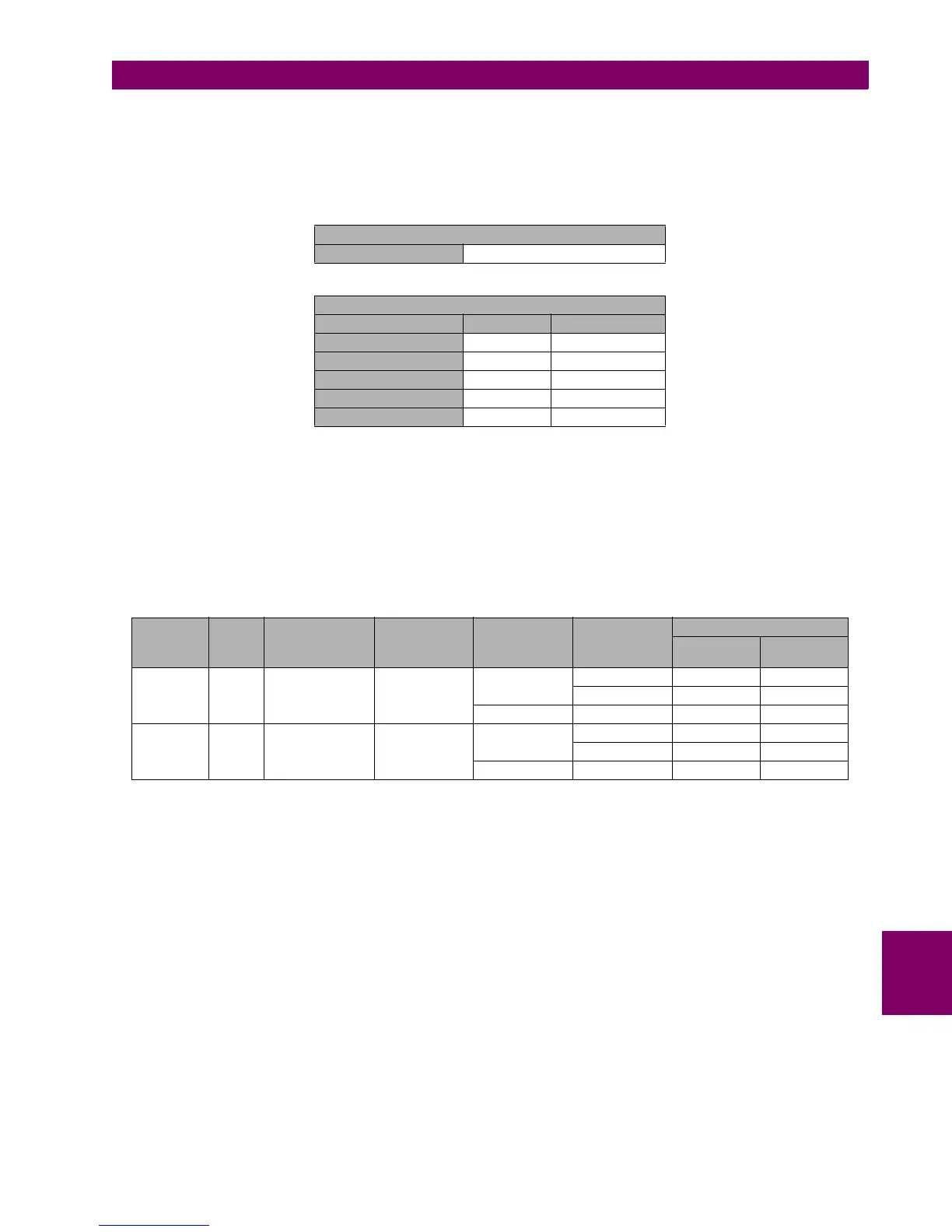
GENERAL SETTINGS
Nominal Frequency 50 Hz
ELEMENT SETTINGS
FREQUENCY (81) 81U 81O
Function ENABLED ENABLED
Pickup Level 47.50 Hz 52.50 Hz
Trip Delay 2.00 sec 2.00 sec
Reset Delay 0.00 sec 0.00 sec
Minimum Voltage 30 V 30 V
ELEMENTS PHASE PICKUP LEVEL
(HZ)
TRIP DELAY
(SECONDS)
APPLIED
VOLTAGE (V)
FREQUENCY
THRESHOLDS
TRIPPING TIME (S)
THEORETICA
L
ADMISSIBLE
81U VII 47.5 2 80 48 Hz No trip NA
46 Hz 2 [1.9 –2.2]
25 46 Hz No trip NA
81 O VII 52.5 2 80 52 Hz No trip NA
54 Hz 2 [1.9 –2.2]
25 54 Hz No trip NA

 Loading...


