5-104 F650 Digital Bay Controller GE Multilin
5.6 INPUTS/OUTPUTS 5 SETPOINTS
5
5.6.3 INPUTS
5.6.3.1 INPUT SETPOINTS DESCRIPTION
Input Activation Voltage Threshold: The range of this value goes from 0 to 255 volts. There is a single setpoint for all
inputs in the same group (inputs sharing the same common). In mixed and supervision boards there are two groups of
inputs, called A and B.
Debounce Time: This is the debounce time set for inputs (1 to 50 ms). The debounce time is the time window for input
filtering. If an input suffers a change of level that lasts less than this set time, the change will not be considered. There is a
single setpoint for all inputs in the same group.
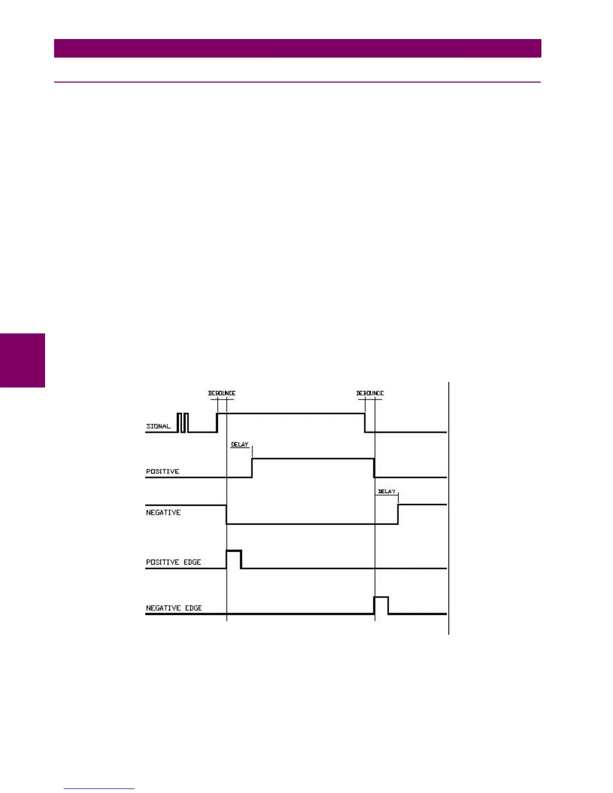
Input Type: Type of logic associated to the physical input. Possible setpoints are, positive and negative.
Positive and Negative setpoints correspond to signals that re activated or deactivated with the input level, considering the
delay setpoint. Positive-edge, and Negative-edge setpoints correspond to signals that are activated with the change of the
input signal; in this case, the Delay Input Time will not be considered, only the Debounce Time; this edge signals are
deactivated automatically after one PLC scan cycle. shows the types of signals associated to the different input
configuration types.
Delay Input Time: This is the delay applied to the input signal; the default value is zero, meaning no delay; the setpoint
range is 0 to 60000 milliseconds (1 minute). This setpoint is used in slow switchgear applications.
This is not a grouped setpoint; there is a different setpoint for each input. It is important to distinguish between this delay
input time and the debounce time used for filtering undesired transients in the input signal. The Debounce time is always
added to the delay input time.
Figure 5–29: INPUT LOGIC TYPES

 Loading...


