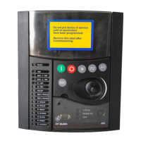
1-8 F650 Digital Bay Controller GE Multilin
1.2 OVERVIEW 1 GETTING STARTED
1
1.2.3 SOFTWARE ARCHITECTURE
The firmware (software embedded in the relay) has been designed using object oriented programming
techniques (OOP). These techniques are based on the use of objects and classes, and provide the software
architecture with the same characteristics as the hardware architecture, i.e., modularity, scalability and
flexibility.
1.2.4 COMMUNICATIONS ARCHITECTURE
The main processor performs protection, control, and communication functions, incorporating two internal pro-
cessors, one for generic use and a second one dedicated for communications.
A dedicated serial port is used for communication between the main processor and the human-machine inter-
face. Serial connection provides great immunity against electromagnetic disturbances, thus increasing system
safety.
All F650 units incorporate an RS232 serial port on the front of the relay. There is also a possibility to incorpo-
rate up to two additional communication modules on the rear.
One of the modules provides asynchronous serial communications, using different physical media (RS485,
plastic or glass fiber optic) depending on the selected model. The module incorporates two identical ports,
COM1 and COM2. COM2 port is multiplexed with the front port. Additionally, this module may incorporate a
glass fiber optic port for CAN BUS communications, used for the connection to the Remote CAN BUS I/O mod-
ule. This feature allows increasing up to 100% the I/O capability, when the maximum number of I/Os available
inside the relay (up to 32 inputs and 16 outputs) is not enough for a specific application.
Available options are:
Table 1–1: TABLE 1-1 REAR SERIAL COMMUNICATIONS BOARD 1
The other module provides Ethernet communications (COM3 port), using 10/100BaseTX (self-negotiable speed) or
100BaseFX connectors, depending on the selected model. Most complete models include a double redundant 100BaseFX
fiber optic port. Redundancy is provided at a physical media level; the unit incorporates internally duplicated and
independent controllers for extended system reliability and accessibility.
Board Code Functionality
F Without additional communication ports
A
Two RS485 ports
P Two Plastic F.O. ports
G Two Glass F.O. ports
X Two RS485 ports and a CAN port for remote CAN Bus Inputs/Outputs
Y Two Plastic F.O. ports and a CAN port for remote CAN Bus Inputs/Outputs
Z Two Glass F.O. ports and a CAN port for remote CAN Bus Inputs/Outputs

 Loading...