GE Multilin F650 Digital Bay Controller 5-9
5 SETPOINTS 5.2 PRODUCT SETUP
5
Snapshot Events: This setpoint enables or disables the snapshot event generation for the oscillography unit.
EXAMPLE
For a Max. Number Osc. of 4, each record will store 1Mbyte / 4 = 262144 bytes.
For this example, the number of samples per oscillography record is 262144 bytes / 38 bytes = 6898 samples per stored
oscillo.
If we set the relay to 64 samples per cycle, each record will store up to 6898 / 64 = 107.78 signal cycles. This value
expressed in terms of time would be:
For 50 Hz: 107.78 cycles x 20 ms/cycle =2.155 seconds.
For 60 Hz: 107.78 cycles x 16.67 ms/cycle =1.796 seconds.
5.2.4.3 OSCILLOGRAPHY STATES
States associated to the oscillography module (“Actual >Metering>Records Status>Oscillography”), are shown in Table
5–11:
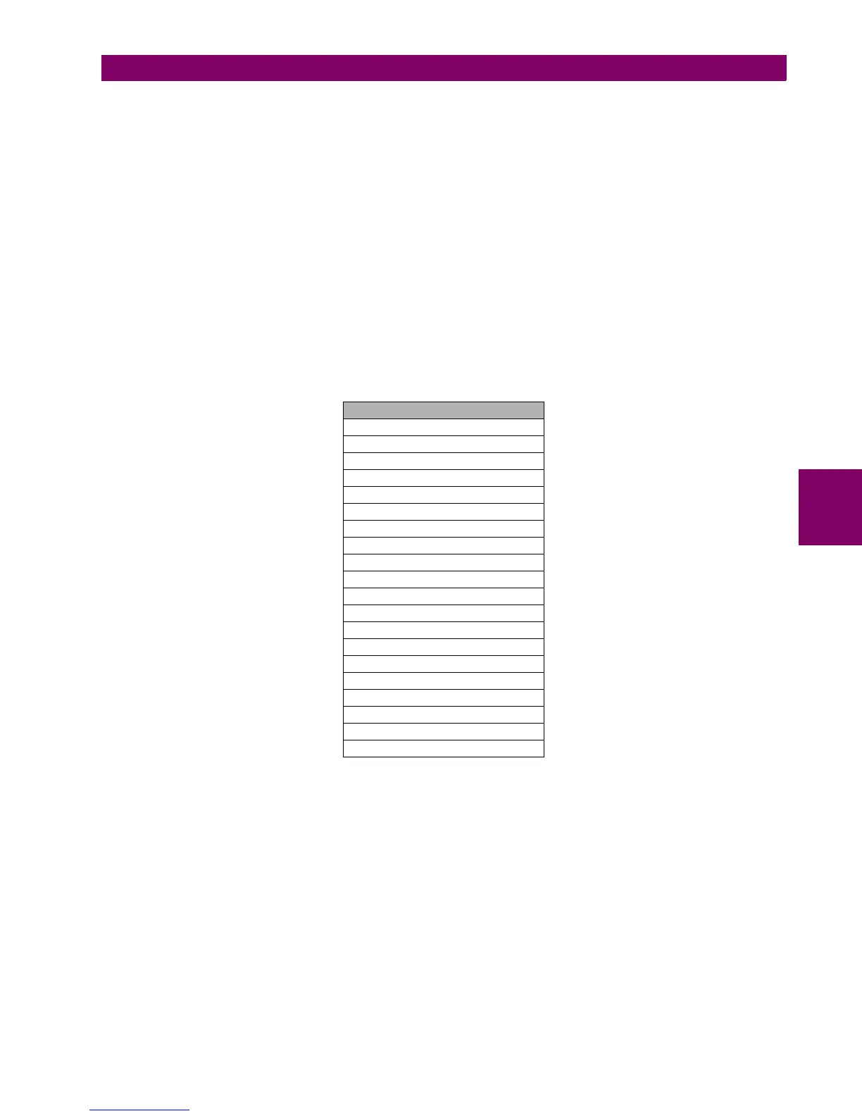
Table 5–11: OSCILLOGRAPHY STATES
OSC DIGITAL CHANNEL XX: These states are configured at “setpoints>Relay configuration>Oscillography”. Each of
these states can be associated to any protection state or to any virtual output. Each oscillography record will reflect the
changes experienced by this state during the record.
OSCILLO TRIGGER: The activation of this state will produce the oscillography record capture. Each record will contain a
percentage of its capacity to store prefault information. This percentage can be selected in the Trigger Position setpoint,
and the rest of the record capacity will store post-fault information.
NUMBER OF TRIGGERS: This is the number of the most recent oscillography record stored in the relay in COMTRADE
format. The range is 0 to 999.
CYCLES PER RECORD: This state contains the number of cycles that will be stored in each oscillography record.
Although the number of cycles can be a decimal digit, the record will represent only the integer part.
OSCILLOGRAPHY STATES
OSC DIG CHANNEL 1
OSC DIG CHANNEL 2
OSC DIG CHANNEL 3
OSC DIG CHANNEL 4
OSC DIG CHANNEL 5
OSC DIG CHANNEL 6
OSC DIG CHANNEL 7
OSC DIG CHANNEL 8
OSC DIG CHANNEL 9
OSC DIG CHANNEL 10
OSC DIG CHANNEL 11
OSC DIG CHANNEL 12
OSC DIG CHANNEL 13
OSC DIG CHANNEL 14
OSC DIG CHANNEL 15
OSC DIG CHANNEL 16
OSCILLO TRIGGER
NUMBER OF TRIGGERS
CYCLES PER RECORD
AVAILABLE RECORDS

 Loading...


