5-136 F650 Digital Bay Controller GE Multilin
5.9 LOGIC CONFIGURATION (PLC EDITOR) 5 SETPOINTS
5
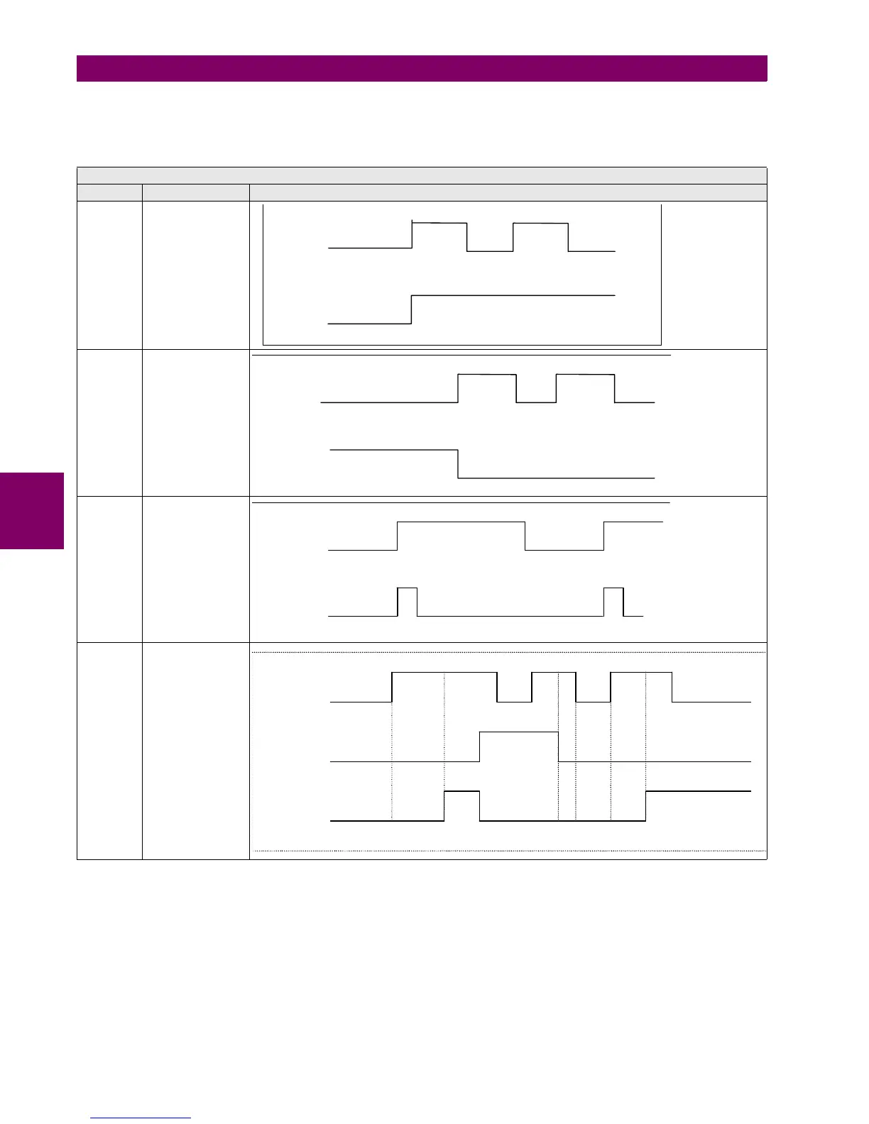
Example of logic signals in F650 logic configuration:
Table 5–99: LOGIC SIGNALS IN F650
LOGIC SIGNALS EXAMPLES
SIGNAL DESCRIPTION TIME DIAGRAM
SET When the input
signal is set to 1 the
output signal
remain fixed to 1 till
a reset signal is
received.
RESET When the input
signal is reset to 1
the output signal
remain fixed to 0.
ONS The input signal is
pulsed. The width of
the output pulse will
be the same as that
of the PLC cycle
TIMER With selectable time
(MASK), one SET
input and one
RESET input
1
Input
0
1
Output
0
1
Input
0
1
Output
0
1
Input
0
1
Output
0
1
SET input
0
1
RESET input
0
1
Output
0
T
ms
T1 T
T1+T2=T

 Loading...


