GE Multilin F650 Digital Bay Controller 5-103
5 SETPOINTS 5.6 INPUTS/OUTPUTS
5
5.6.2 CONTROL SETPOINTS FOR INPUTS/OUTPUTS
Configuration of setpoints relative to inputs and outputs can only be accessed through EnerVista 650 Setup
software, and not via the HMI. For this purpose, the user must access Setpoint > Inputs/Outputs > Contact I/O > Board
X, being X the corresponding I/O board.
setpoints relative to I/O boards are described in :
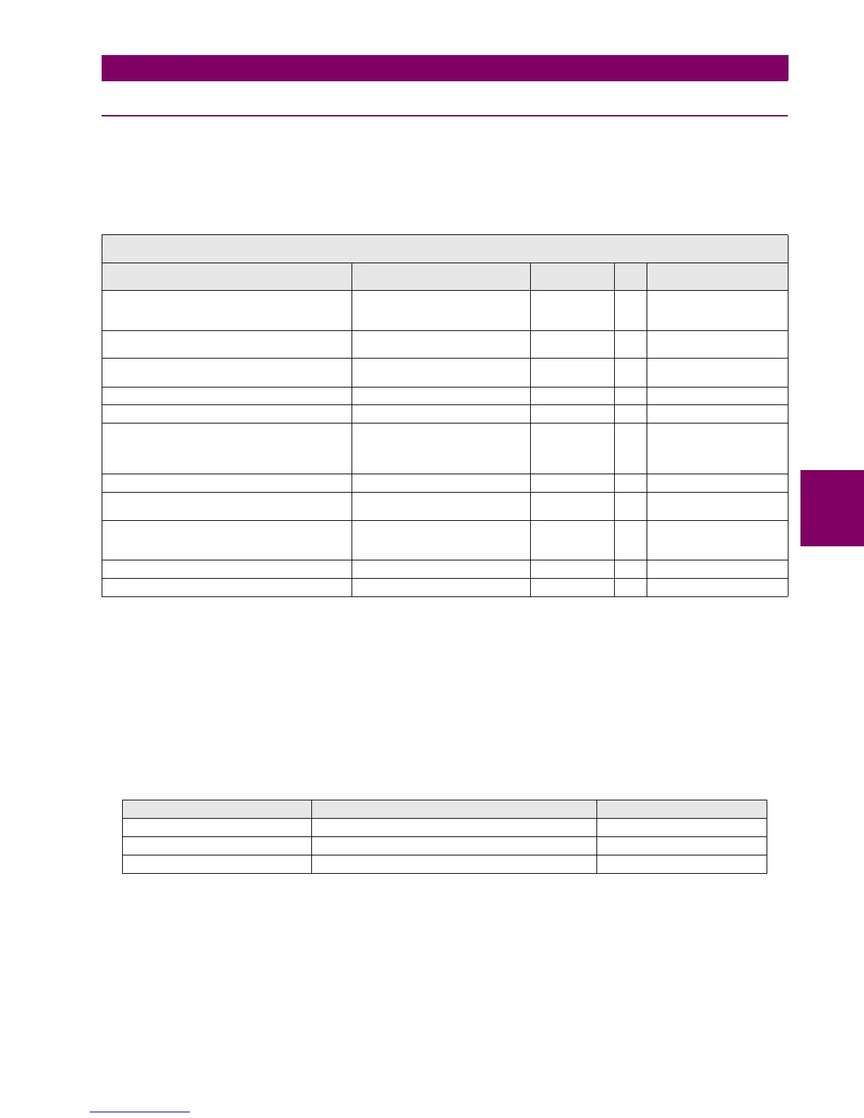
Table 5–85: I/O BOARD SETPOINTS
The snapshot event setpoint enables or disables the snapshot event generation for this unit.
Being:
X F, G, H or J, the I/O board name, depending on the Relay model.
F and G are internal Relay boards, and H and J are additional boards available in CIO modules (remote Bus CAN I/O
module).
For the I/O board selection in the relay model, associated digits to each board type are as follows:
Table 5–86: I/O BOARD TYPE
CCY Is the name used for inputs in I/O boards
Mixed, 16 digital inputs: CC1….CC16
Supervision: 8 digital inputs: CC1,..., CC8
0Z Is the name used for the different outputs in I/O boards, 8 outputs available for any of the two types of board
(01,…., 08)
SETPOINT > INPUTS/OUTPUTS > CONTACT I/O >
BOARD F > BOARD G > BOARD H > BOARD J
SETPOINT DESCRIPTION NAME DEFAULT
VALUE
STE
P
RANGE
I/O board type (available only for CIO modules) I/O Board Type_H NONE N/A [NONE,
16 INP + 8OUT,
8 INP + 8OUT + SUPV]
Input activation voltage threshold
Group A
Voltage Threshold A_X 80 1 V [0 : 255]
Input activation voltage threshold
Group B
Voltage Threshold B_X 80 1 V [0 : 255]
Debounce time for Group A Debounce Time A_X 15 1 ms [1 : 50]
Debounce time for Group B Debounce Time B_X 15 1 ms [1 : 50]
Input type Input Type_X_CCY (CCY) POSITIVE N/A [POSITIVE-EDGE,
NEGATIVE-EDGE,
POSITIVE,
NEGATIVE]
Input signal time delay Delay Input Time_X_CCY (CCY) 0 1 ms [0 : 60000]
Output logic type Output Logic_X_0Z POSITIVE N/A [POSITIVE,
NEGATIVE]
Output type Output Type_X_0Z NORMAL N/A [NORMAL,
PULSE,
LATCH]
Output pulse length Pulse Output Time_X_0Z 10000 1 ms [0 : 60000]
Snapshot event generation Snapshot Events ENABLED N/A [DISABLED – ENABLED]
ASSOCIATED DIGIT ENERVISTA 650 Setup BOARD setpointS BOARD TYPE
0 NONE None
1 16 INP+ 8OUT Mixed
2 8 INP +8 OUT +SUPV Supervision

 Loading...


