GE Multilin F650 Digital Bay Controller 5-135
5 SETPOINTS 5.9 LOGIC CONFIGURATION (PLC EDITOR)
5
5.9.2 THEORY OF OPERATION
5.9.2.1 DESCRIPTION
As already mentioned in the introduction, this tool uses FBD mode of IEC 61131-3 standard. For this purpose we have
defined a series of basic operations with illustrations below.
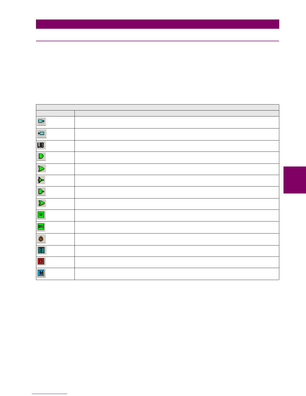
The basic operations available in PLC Editor are located in the tool bar of the application and are as follows:
Table 5–98: PLC EDITOR BASIC OPERATION IN F650
PLC EDITOR BASIC OPERATION
ICONS IN SCREEN DESCRIPTION
INPUT TO LOGIC: Selection of the digital input to the logic. (All available internal status can be used as logic
inputs)
OUTPUT FROM LOGIG: Virtual output built with internal logic. (Up to 512)
LIBRARY: Possibility to build blocks of logic in a simple graphic object. OR and AND from 3 to 8 inputs are provided
as libraries.
AND of two digital inputs.
OR of two digital inputs.
NOT of a digital input.
NAND of two digital inputs.
XOR of two digital inputs.
SR: Latch (set-reset): reset dominant.
ONS: signal to pulse an logic input to a signal of one scan cycle length.
TIMER: timer signal with set, reset and mask for timing.
TEXT LABEL: text to customize the logic configuration file.
Flip-Flop D : signal that maintains the actual value frozen during a PLC cycle
MASK: Time mask to be used in timing operations.

 Loading...


