5-58 F650 Digital Bay Controller GE Multilin
5.4 PROTECTION ELEMENTS 5 SETPOINTS
5
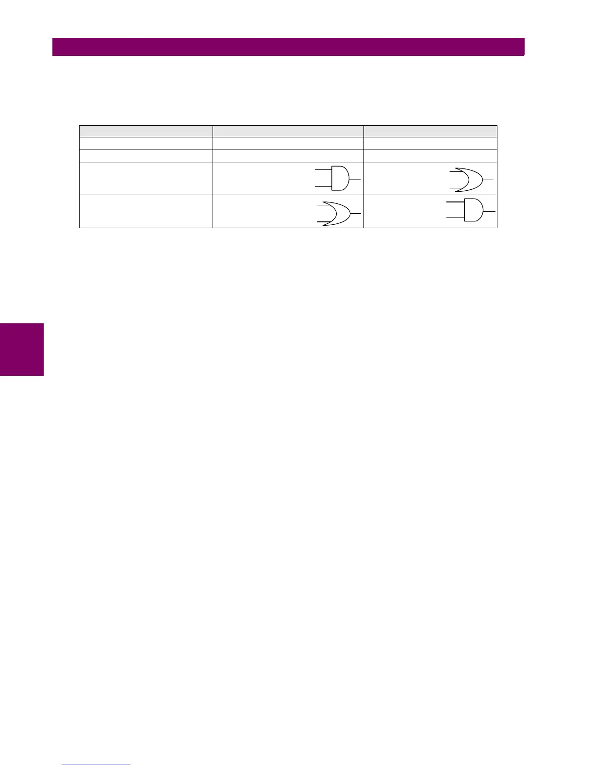
The following table shows the management of the unit output signals (block and permission) depending on the
Polarization Type setpoint.
Table 5–53: OUTPUT SIGNALS MANAGEMENT ACCORDING TO THE POLARIZTION TYPE SETPOINT
The configuration of the signals required for blocking the Ground overcurrent elements from the signals provided by the
Ground directional unit is made at Setpoint > Relay Configuration > Protection Elements using inverted operation
signals to block the trip.
For example, to block the ground time delayed units:
GROUND TOC1 BLOCK = NOT (GROUND DIR1 OP)
GROUND TOC2 BLOCK = NOT (GROUND DIR2 OP)
GROUND TOC3 BLOCK = NOT (GROUND DIR3 OP)
To block the Ground Instantaneous units:
GROUND IOC1 BLOCK = NOT (GROUND DIR1 OP)
GROUND IOC2 BLOCK = NOT (GROUND DIR2 OP)
GROUND IOC3 BLOCK = NOT (GROUND DIR3 OP)
POLARIZATION SETPOINT GROUND DIR BLOCK SIGNAL GROUND DIR OP SIGNAL
Vo V
0
< Ajs. POL V THRESHOLD Permission V
0
Ip I
P
< 5 mA Permission I
P
Vo + Ip V
0
< POL V THRESHOLD
I
P
< 5 mA
Permission V
0
Permission I
P
Vo * Ip V
0
< POL V THRESHOLD
I
P
< 5 mA
Permission V
0
Permission I
P

 Loading...


