GE Multilin F650 Digital Bay Controller 9-5
9 COMMISSIONING 9.5 POWER SUPLY TESTING
9
9.5POWER SUPLY TESTING
Feed the relay to the minimum and maximum voltage. For each voltage value, verify that the alarm relay is activated when
there is voltage, and it is deactivated when there is no feed. If the power supply source incorporates AC feed, this test will
be performed also for VAC.
If the relay incorporates a redundant power supply, these tests shall be performed on both power supplies.
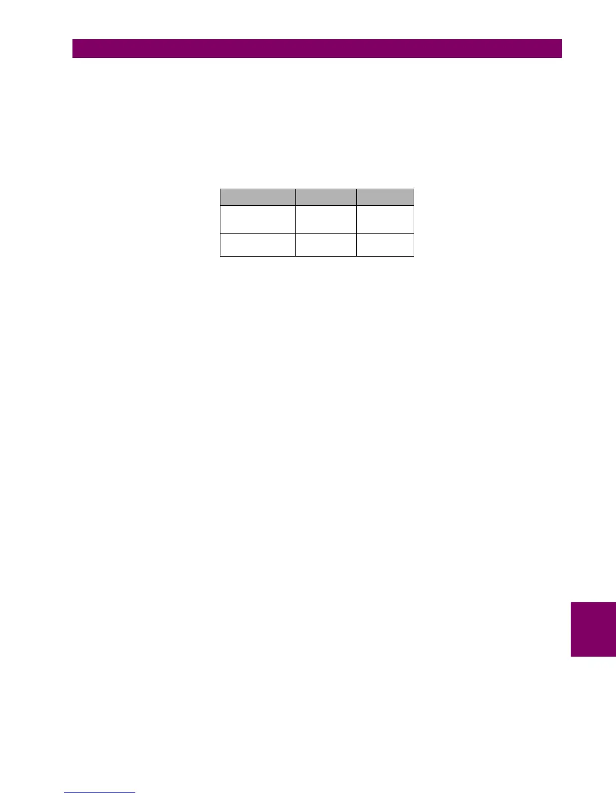
Voltage values to be applied will be the ones indicated below according to the relay model:
NOTE: Codes HIR and LOR correspond to a redundant power supply
SUPPLY V MIN. V MAX.
HI/HIR
110-250 Vdc
120-230 Vac
88 Vdc
96 Vac
300 Vdc
250 Vac
LO/LOR
24-48 Vdc 20 Vdc 57.6 Vdc

 Loading...


