Programming contours | Fundamentals of path functions
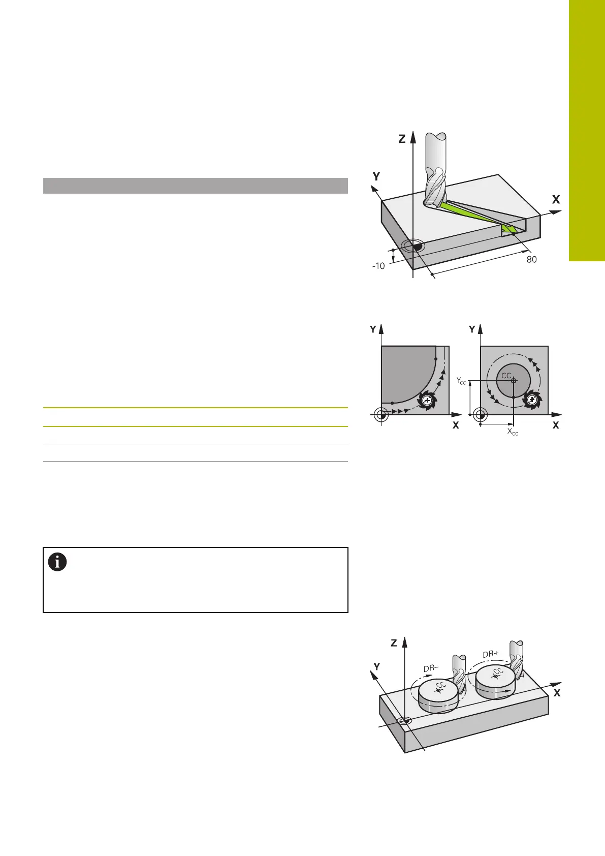
Three-dimensional movement
If the NC block contains three coordinates, the control moves the
tool spatially to the programmed position.
Example
L X+80 Y+0 Z-10
Circles and circular arcs
The control moves two machine axes simultaneously on a circular
path relative to the workpiece. You can define a circular movement
by entering the circle center CC .
Use the path functions for circular arcs to program circles in the
working plane. You define the main plane based on the spindle axis
in the TOOL CALL.
Spindle axis Main plane
Z XY, also UV, XV, UY
Y ZX, also WU, ZU, WX
X YZ, also VW, YW, VZ
Circular motion in another plane
You can also use the Tilt the working plane function or
Qparameters to program circular motions that do not lie in the main
plane.
Further information: "The PLANE function: Tilting the
working plane (option 8)", Page 431
Further information: "Principle and overview of
functions", Page 268
Direction of rotation DR for circular movements
When a circular path has no tangential transition to another contour
element, enter the direction of rotation as follows:
Clockwise direction of rotation: DR-
Counterclockwise direction of rotation: DR+
5
HEIDENHAIN | TNC620 | Klartext Programming User's Manual | 01/2022
141
 Loading...


