Programming Qparameters | Describing contours with mathematical functions
Programming fundamental operations
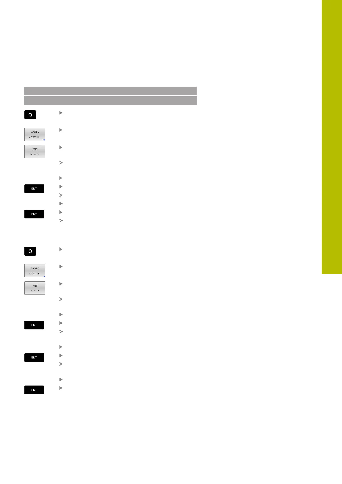
Example: Assignment
16 FN 0: Q5 = +10
17 FN 3: Q12 = +Q5 * +7
Select the Q parameter function: Press the Q key
Select basic mathematical functions by pressing
the BASIC ARITHM. soft key
To select the ASSIGN Q parameter function: Press
the FN 0 X = Y soft key
The control asks you for the number of the result
parameter.
Enter 5 (number of Q parameter)
Confirm with the ENT key
The control asks you for the value or parameter.
Enter 10 (value)
Confirm with the ENT key
As soon as the control reads the NC block, the
value 10 is assigned to the parameter Q5.
Example: Multiplication
Select the Q parameter function: Press the Q key
Select basic mathematical functions by pressing
the BASIC ARITHM. soft key
To select the MULTIPLICATION Q parameter
function, press the FN 3 X * Y soft key
The control asks you for the number of the result
parameter.
Enter 12 (number of Q parameter)
Confirm with the ENT key
The control asks you for the first value or
parameter.
Enter Q5 (parameter)
Confirm with the ENT key
The control asks you for the second value or
parameter.
Enter 7 for the second value
Confirm with the ENT key
9
HEIDENHAIN | TNC620 | Klartext Programming User's Manual | 01/2022
275
 Loading...


