Fundamentals | NC fundamentals
Reference systems
For the control to move an axis in accordance with a defined path, it
requires a reference system.
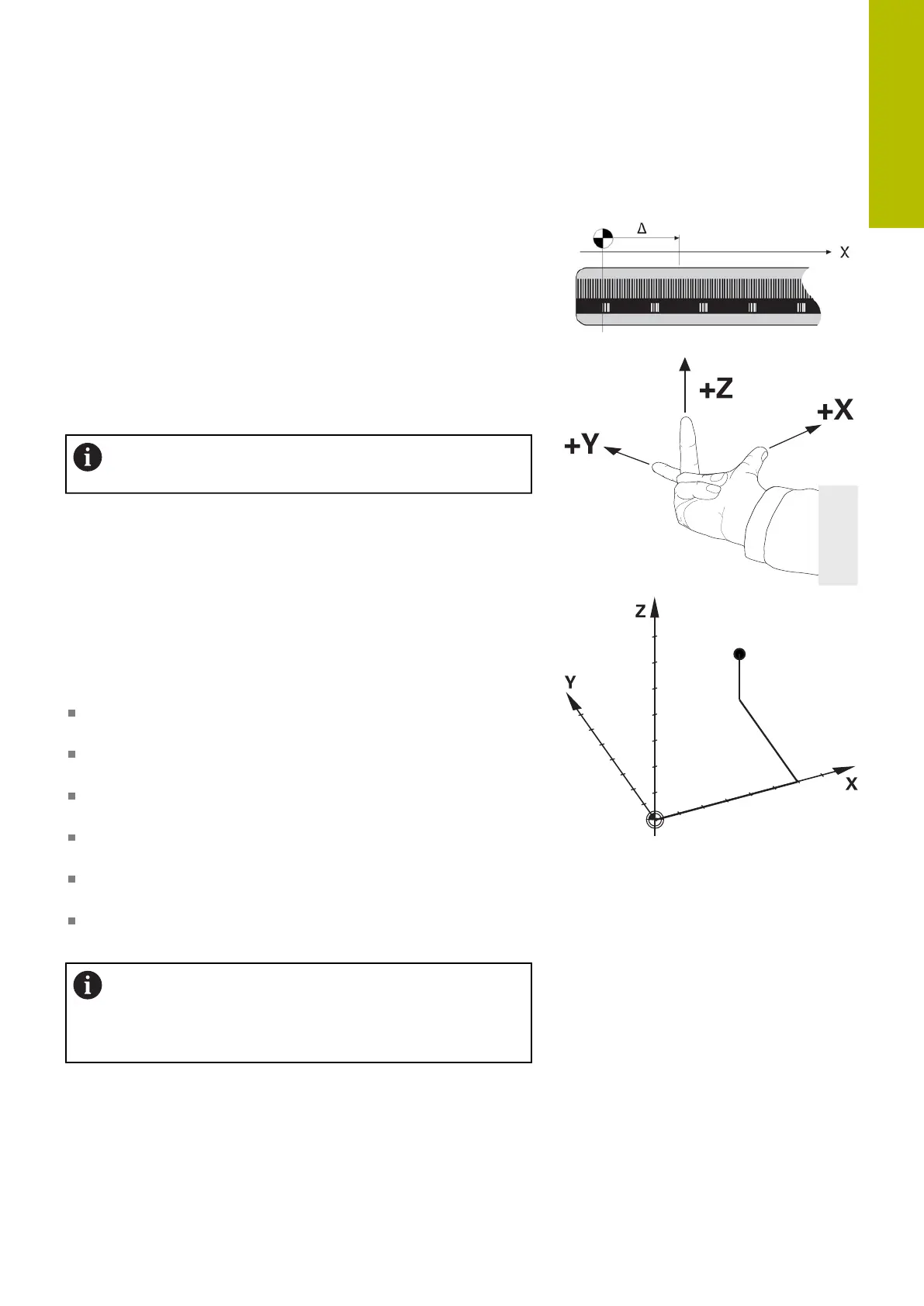
A paraxially mounted linear encoder on a machine tool serves
as a simple reference system for linear axes. The linear encoder
represents a number ray, a one-dimensional coordinate system.
To approach a point on the plane, the control requires two axes and
therefore a reference system with two dimensions.
To approach a point in space, the control requires three axes and
therefore a reference system with three dimensions. If these three
axes are arranged perpendicularly to each other, this creates a
three-dimensional Cartesian coordinate system.
According to the right-hand rule the fingertips point in the
positive directions of the three principal axes.
For a point to be uniquely determined in space, a coordinate origin
is needed in addition to the arrangement of the three dimensions.
The common intersection serves as the coordinate origin in a 3-D
coordinate system. This intersection has the coordinates X+0, Y+0,
and Z+0.
In order, for example, for the control to always perform a tool
change at the same position, as well as always execute a machining
operation referenced to the current workpiece position, the control
must be able to differentiate between different reference systems.
The control differentiates between the following reference systems:
Machine coordinate system M-CS:
Machine Coordinate System
Basic coordinate system B-CS:
Basic Coordinate System
Workpiece coordinate system W-CS:
Workpiece Coordinate System
Working plane coordinate system WPL-CS:
Working Plane Coordinate System
Input coordinate system I-CS:
Input Coordinate System
Tool coordinate system T-CS:
Tool Coordinate System
All reference systems build upon each other. They are
subject to the kinematic chain of the specific machine
tool.
The machine coordinate system is the reference system.
3
HEIDENHAIN | TNC620 | Klartext Programming User's Manual | 01/2022
77