Multiple-axis machining | The PLANE function: Tilting the working plane (option 8)
11
Examples
Machine with C rotary axis and A tilting table. Programmed
function: PLANE SPATIAL SPA+0 SPB+45 SPC+0
Limit switch Start position SYM = SEQ Resulting axis position
None A+0, C+0 Not prog. A+45, C+90
None A+0, C+0 + A+45, C+90
None A+0, C+0 – A–45, C–90
None A+0, C–105 Not prog. A–45, C–90
None A+0, C–105 + A+45, C+90
None A+0, C–105 – A–45, C–90
–90 < A < +10 A+0, C+0 Not prog. A–45, C–90
–90 < A < +10 A+0, C+0 + Error message
–90 < A < +10 A+0, C+0 – A–45, C–90
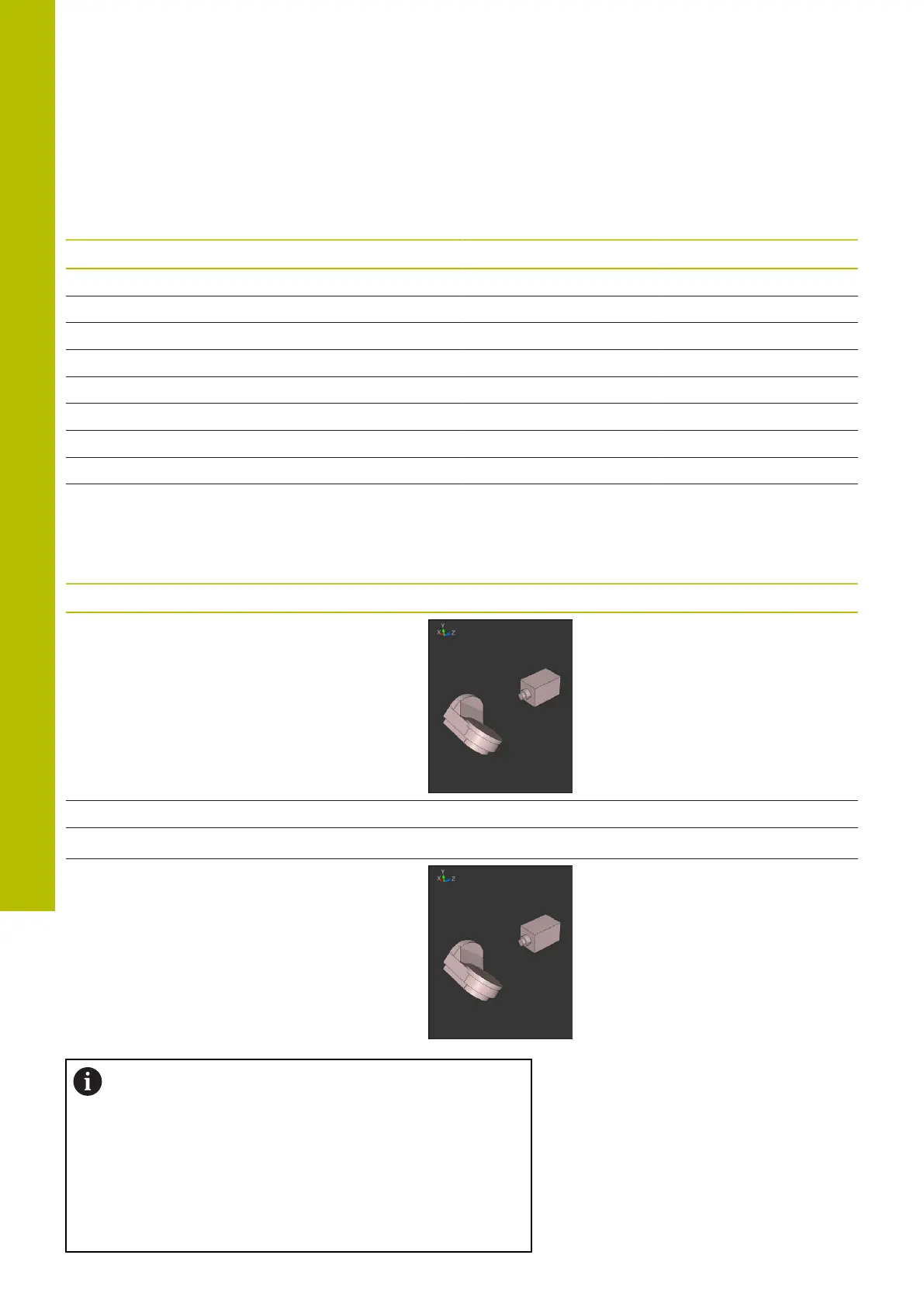
Machine with B rotary axis and A tilting table (limit switches: A
+180 and –100). Programmed function: PLANE SPATIAL SPA-45
SPB+0 SPC+0
SYM SEQ Resulting axis position Kinematics view
+ A–45, B+0
- Error message No solution in limited range
+ Error message No solution in limited range
- A–45, B+0
The position of the symmetry point is contingent on
the kinematics. If you change the kinematics (such as
switching the head), then the position of the symmetry
point changes as well.
Depending on the kinematics, the positive direction
of rotation of SYM may not correspond to the positive
direction of rotation of SEQ. Therefore, ascertain the
position of the symmetry point and the direction of
rotation of SYM on each machine before programming.
456
HEIDENHAIN | TNC620 | Klartext Programming User's Manual | 01/2022