APPENDIX 22
────────────────────────────────────────────────────
Appendix 3 Active Power Consumption/Regeneration, and Reactive Power and Power Factor Lead and Lag
────────────────────────────────────────────────────
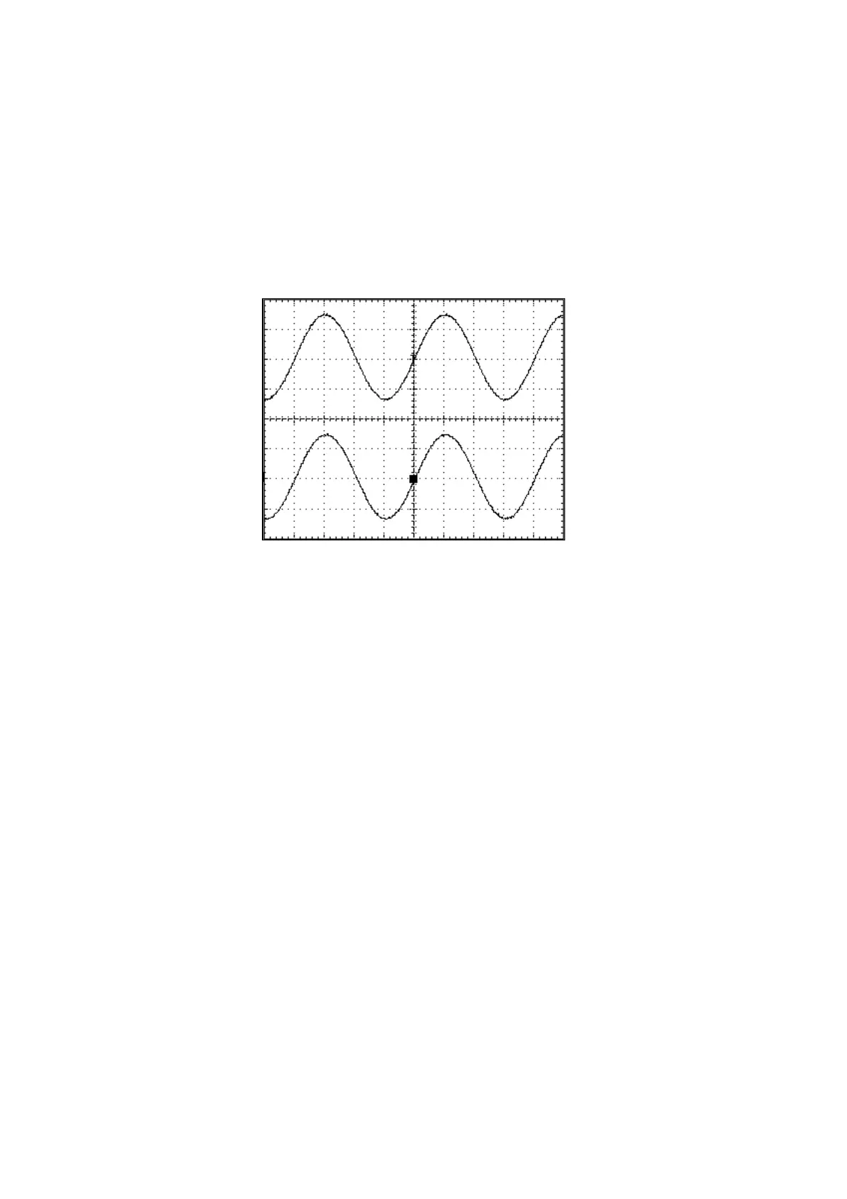
Input Waveform Sine Wave
Reference Differences in measured values
Note that some voltage and current waveforms will yield different results for
reactive power and power factor measurements when each of the
measurement methods described above is selected.
・When the voltage and current waveforms are both sine waves (or have
identical waveforms)
In the case of a sine wave such as that shown in the diagram, only the base
wave is present, so the same measured values will be obtained, regardless of
which measurement method is used.
・When the voltage waveform is a sine wave and the current waveform is a
unique distorted waveform (There are harmonic wave components in the
current.)
In the case of a sine wave such as that shown in the diagram, using the
reactive power meter method will yield a small reactive power value and a
large (good) power factor.
This difference arises as a result of the principles described below.
When the reactive power meter method is not used, in order to determine the
reactive power (var1), the apparent power (VA1) derived from the product of
the actual current and voltage values includes not only the base wave
component but also the harmonic wave components. The power factor in this
case is labelled λ1.
Conversely, when using the reactive power meter method, only components of
the same frequency appear as measured values because the reactive power is
determined directly, like the active power (P). Therefore, in this example, the
current waveform has many harmonic wave components, and the reactive
power (var2) of the component that has the same frequency as the voltage (i.e.,
just the base wave) is smaller than that measured by the method described
above. Because the apparent power (VA2) derived from this P and var2 is also
smaller as a result, the power factor (λ2) increases, since it is derived from
the ratio of the active power and the apparent power.
var1 > var2
VA1 > VA2
λ1<λ2