251
────────────────────────────────────────────────────
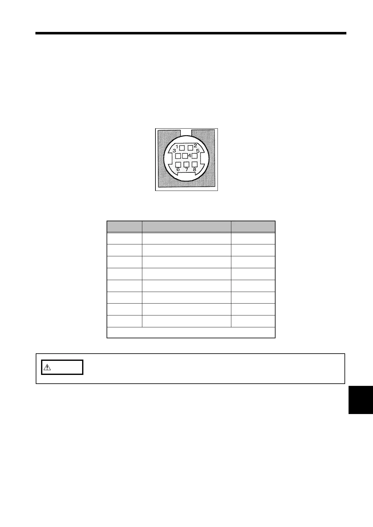
13.2 Structure of the Output Connector
────────────────────────────────────────────────────
1
2
3
4
5
6
7
8
9
0
1
2
3
4
A
Pin Arrangement of D/A Output Connector
Pin No
Signal name Wire color
1
D/A output channel 1 Red
2
D/A output channel 2 White
3
D/A output channel 3 Black
4
D/A output channel 4 Yellow
5
Ground Blue
6
Ground Green
7
Ground Brown
8
Ground Gray
Pins 5 through 8 are common grounds.
CAUTIO
To avoid damage to the unit, do not short the output terminal and do not input
voltage to the output terminal.
3.2 Structure of the Output Connector
The output resistance of the output connector is about 100 Ω.
Any oscilloscope or recorder that is connected to the power meter should have
an input resistance of at least 100 kΩ.
The pin arrangement of the connector is shown below.