31
────────────────────────────────────────────────────
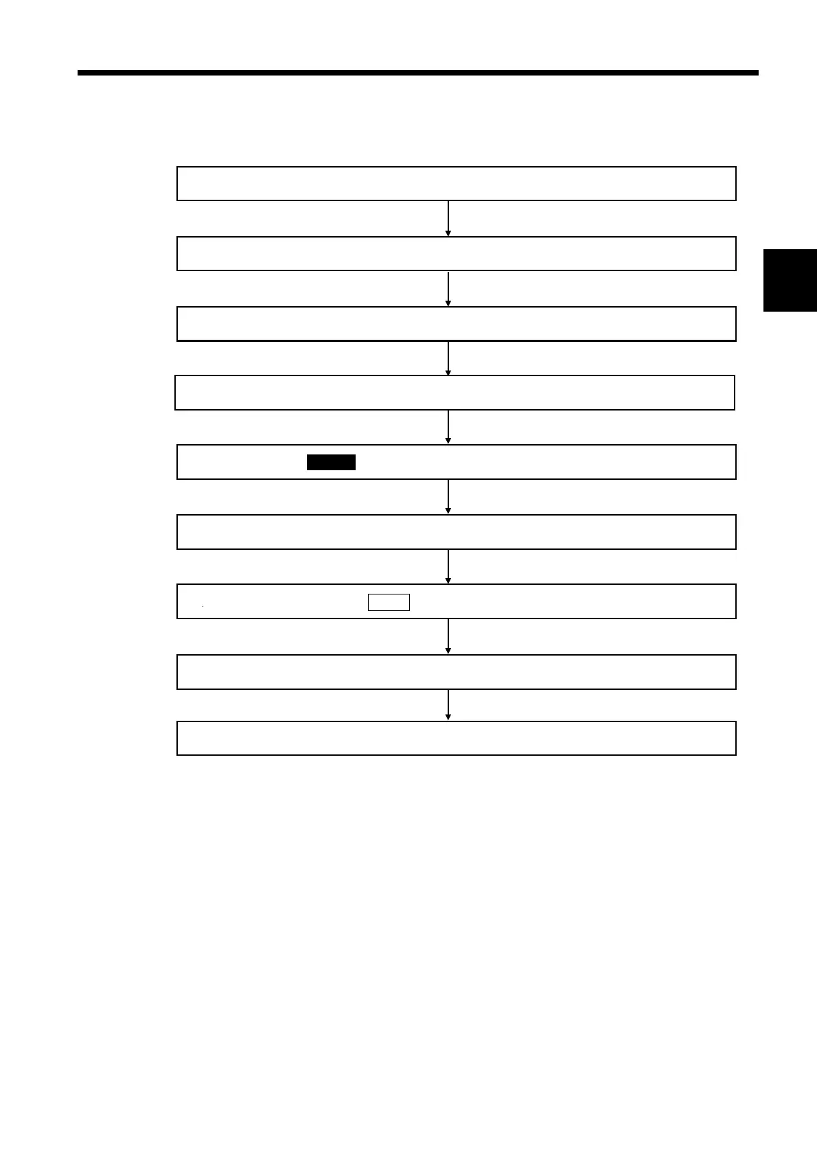
4.3 Flow Chart of Basic Operating Procedure
────────────────────────────────────────────────────
1
2
3
4
5
6
7
8
9
10
11
12
13
14
A
Set the wiring that is suited for the line being measure
Press the CHECK key so that the "wiring" diagram screen is displaye
Press the EXEC. key and check for incorrect wirin
If incorrect wiring is detected, correct it as instructe
Confirm that all wiring has been completed correctl
Wire the power meter to the line being measured according to the wiring diagram
Select the "Setting" mode on the "Initial" scree
Set the frequency of the line being measured
Return to the "Initial" screen, and select the target measurement mod
.3 Flow Chart of Basic Operating Procedure