141
────────────────────────────────────────────────────
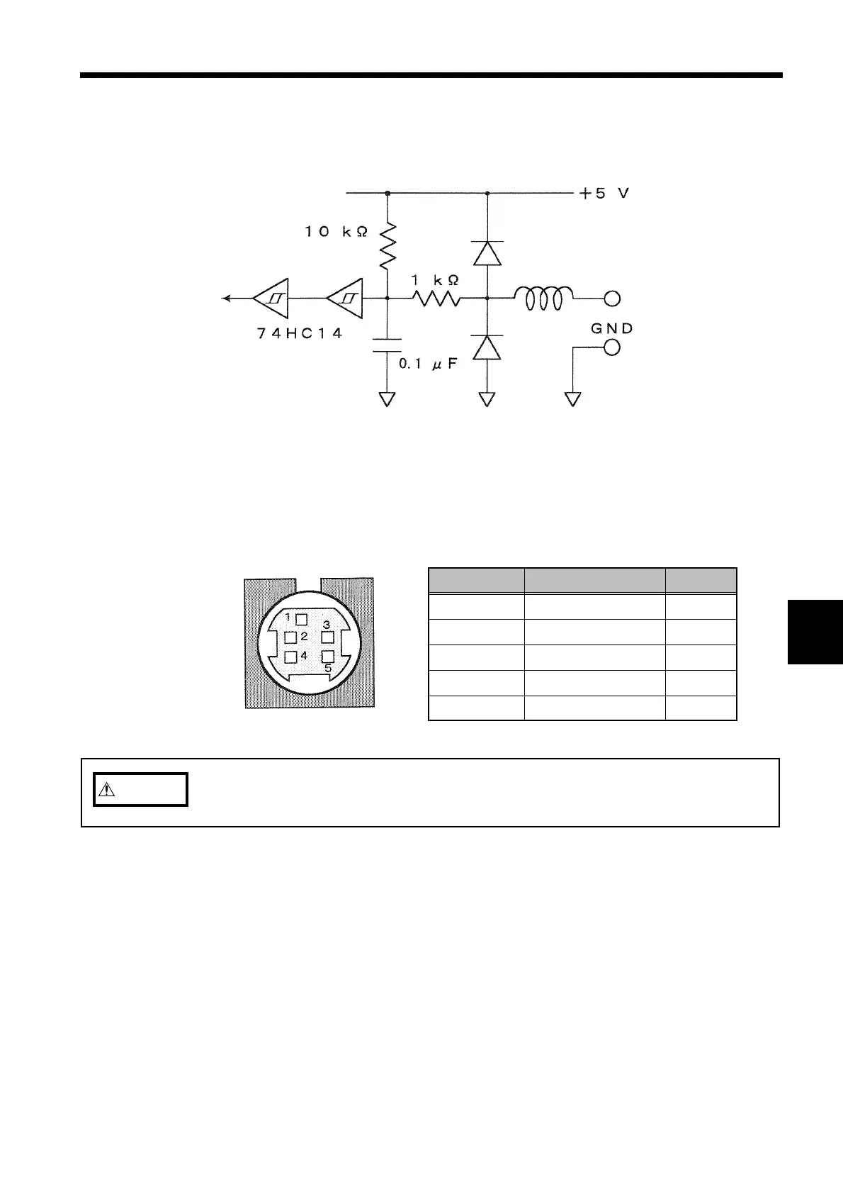
9.2 Structure of the Remote Control Jack
────────────────────────────────────────────────────
1
2
3
4
5
6
7
8
9
10
11
12
13
14
A
Input termina
Remote Control Jack Circuit
Pin No. Signal name Color
1 Start/stop Red
2 Data reset White
3 Print out Black
4 Floppy save Yellow
5 Ground (common) Blue
CAUTIO
In order to prevent damage to the power meter, do not input voltage that
exceeds 5.5 V.
.2 Structure of the Remote Control Jack
The diagram below shows the circuit diagram of the remote control jack.
Control operation is performed using 0/5 V logic signals or closed/open contact
signals. The pin arrangement of the jack is shown below.