13
────────────────────────────────────────────────────
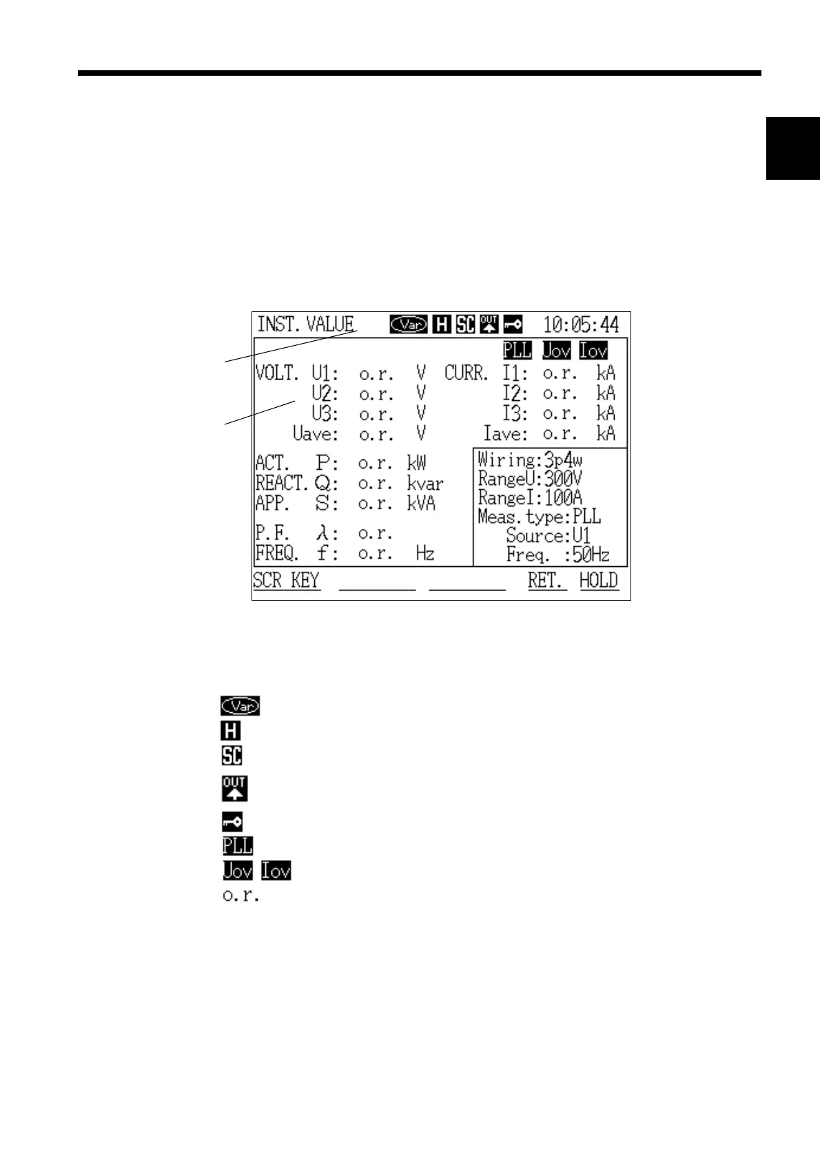
2.2 Screen Configuration
────────────────────────────────────────────────────
1
2
3
4
5
6
7
8
9
10
11
12
13
14
A
Window
Status lin
Screen Display Example
When using the reactive power meter method
Display hold state
Scaling is set
Automatic output is set
(FD auto output, RS-232C automatic output)
Key lock state
PLL unlocked state
Voltage or current is outside of dynamic range
Over-range indication
.2 Screen Configuration
This power meter uses a window system for ease of operation. The screen
configuration is basically the same for all modes. Windows open as necessary.
Setting conditions, the current status, and warning messages when errors
occur are also displayed in windows.
For details on the organization of all of the screens, including the links
between them, refer to item 5 in the Appendices.