146
────────────────────────────────────────────────────
10.2 Information That Can Be Printed Out
────────────────────────────────────────────────────
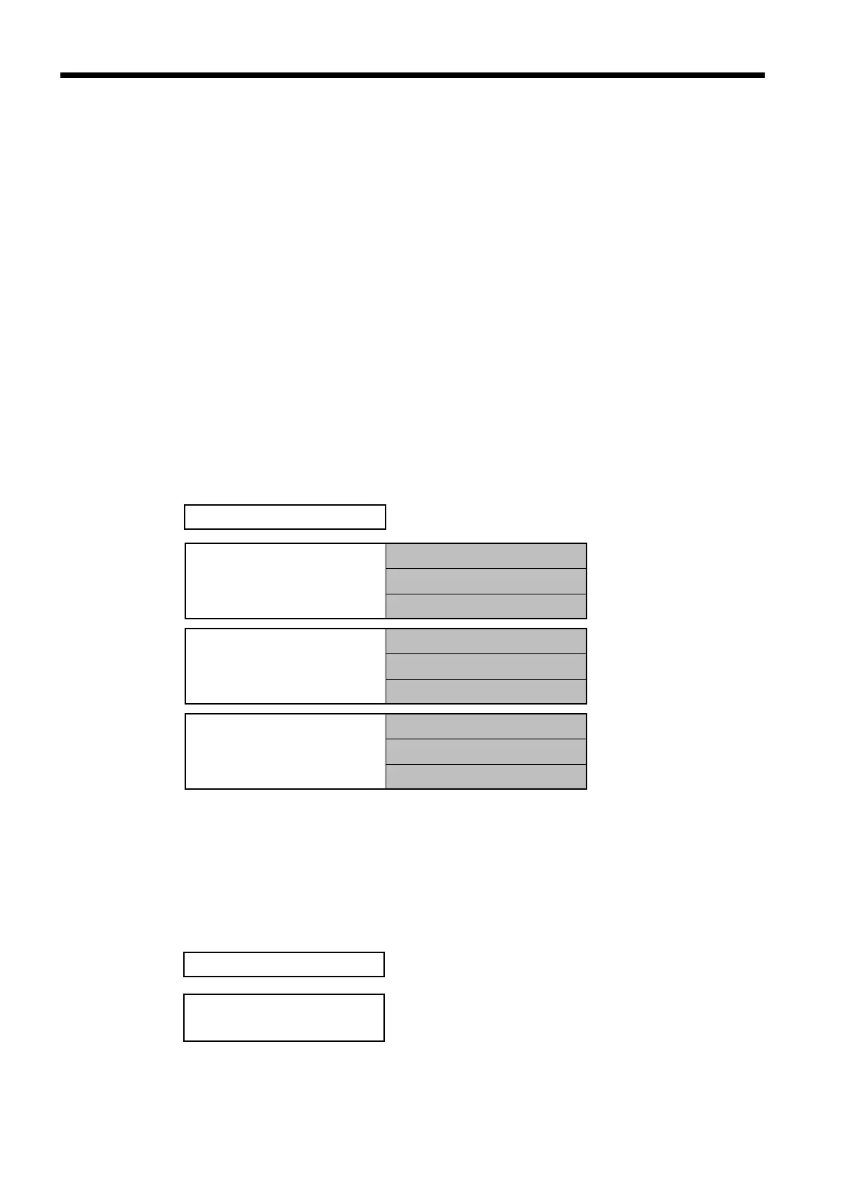
1.Date and time of printing
2.Instantaneous values
Instantaneous value dat
at time of printing
Voltage(U1, U2, U3, Uave
Current(I1, I2, I3, Iave)
Power(P, Q, S, λ, f)
3.Maximum values
Voltage(U1, U2, U3)
Current(I1, I2, I3)
Power(P, Q, S, λ, f)
4.Minimum values
Voltage(U1, U2, U3)
Current(I1, I2, I3)
Power(P, Q, S, λ, f)
1.Date and time of printing
2.Integration start time an
integration elapsed time
0.2 Information That Can Be Printed Out
The setting of which items are to be printed out is done in the print/save items
on the setting screen of each measurement mode. These items also determine
which data is saved to the floppy disk. For specific details on how to make
these settings, refer to the sections on the settings for each measurement
mode.
The items that are set are output in both manual operation and automatic
operation.
The items that are output differ, depending on whether the integrated power
level is measured using the reactive power meter method or not.
All setting conditions can be printed out, whether from the setting screen for a
given measurement mode, or from "Setting" mode.
(1) Measurement data
●"Normal Measurement" mode
* The minimum/maximum value data the time at which each
minimum/maximum value was generated
* Items 3 and 4 reflect data that was tabulated from the point when the data
reset key was pressed until the time of printing.
●"Integrated Measurement" mode