22
────────────────────────────────────────────────────
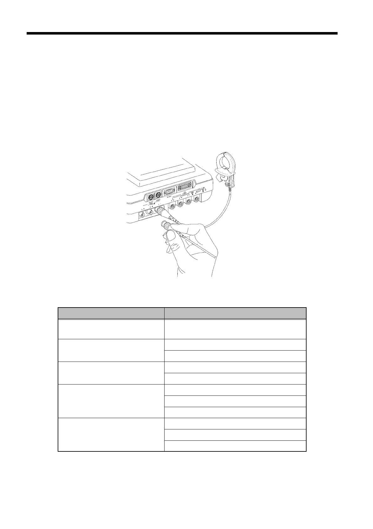
3.3 Connecting the Clamp on Sensors
────────────────────────────────────────────────────
Connecting the Clamp on Sensors
Line being measured Current input connector used (color code)
Single-phase,
two-wire measurement
No. 1 connector (red connector)
Single-phase,
three-wire measurement
No. 1 connector (red connector)
No. 2 connector (yellow connector)
Three-phase, three-wire,
two-current measurement
No. 1 connector (red connector)
No. 2 connector (yellow connector)
Three-phase, three-wire,
three-current measuremen
No. 1 connector (red connector)
No. 2 connector (yellow connector)
No. 3 connector (blue connector)
Three-phase, four-wire
measurement
No. 1 connector (red connector)
No. 2 connector (yellow connector)
No. 3 connector (blue connector)
.3 Connecting the Clamp on Sensors
Use Hioki’s 9291/ 9298 CLAMP ON SENSOR with this power meter.
(1) Connect only the number of clamp on sensors needed for the type of line being
measured.
(2) Align the clamp on sensor connector with the connector guide notch on the
current input connector. While pushing the connector in, turn it to the right
to lock it.