Servo Drive Configuration D1 Servo Drive User Manual
5-30 HIWIN MIKROSYSTEM CORP.
Adjusting phase initialization:
The motor only needs to move for a small
distance to complete phase initialization. After
tuning in step 5 completes, check the tuning
result by the following steps.
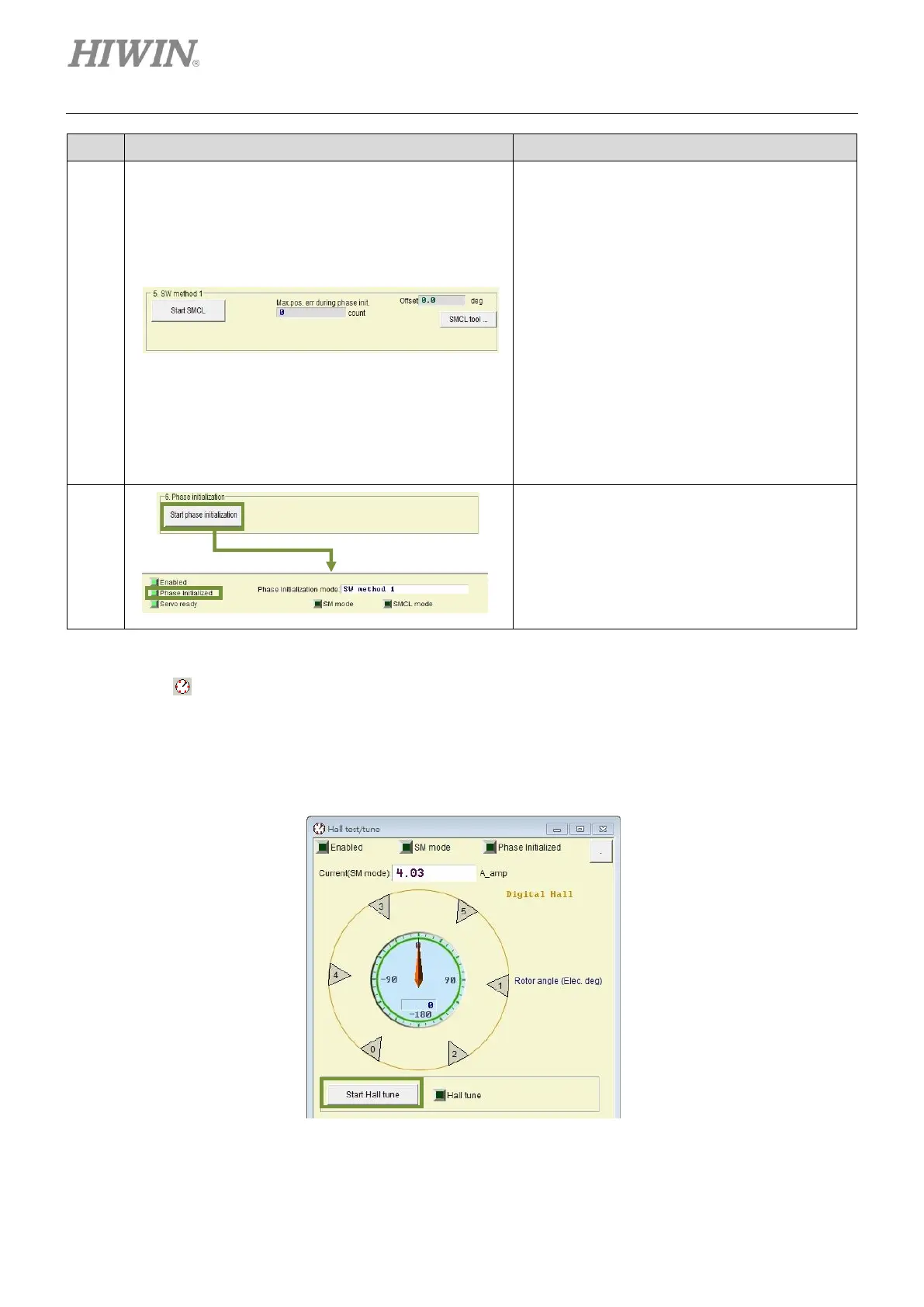
Step 1: Click on Start SMCL button to find
electrical angle.
Step 2: Observe the values in the fields of
Offset and Max. pos. err during
phase init.. Offset shows the result of
finding electrical angle and Max. pos.
err during phase init. shows the
largest movement during the process.
Step 3: Repeat step 1 and 2 to observe if the
offset is within +/- 15 degrees.
Step 4: If offset is too large, click on SMCL
tool… button for advanced tuning.
Executing phase initialization:
Click on Start phase initialization button.
After Phase Initialized indicator becomes
green, it means phase initialization completes.
The servo drive is able to control the motor to
perform closed-loop control.
◼ Phase initialization when digital Hall sensor is used
Click on to open the page for Hall sensor test and tuning. Click on Start Hall tune button. The
servo drive starts to output current to drive motor. Rotor angle (Elec. deg) indicator shows electrical
angle and Hall sensor information (0 to 5). After the motor stops, a message will appear to indicate
the tuning has completed. Then, phase initialization can be started.
Figure5.3.2.1