HIWIN MIKROSYSTEM CORP. 5-39
◆ Function
This input function can only be used in velocity mode and is level triggered. When the input signal is
ON and the motor speed is equivalent to or slower than the speed set for activating brake, the
operation mode will be changed to stand-alone mode and the motor is stopped at current position. The
operation mode is changed back to velocity mode and the motor starts to move as the motor speed is
faster than the speed set for activating brake.
◆ Description
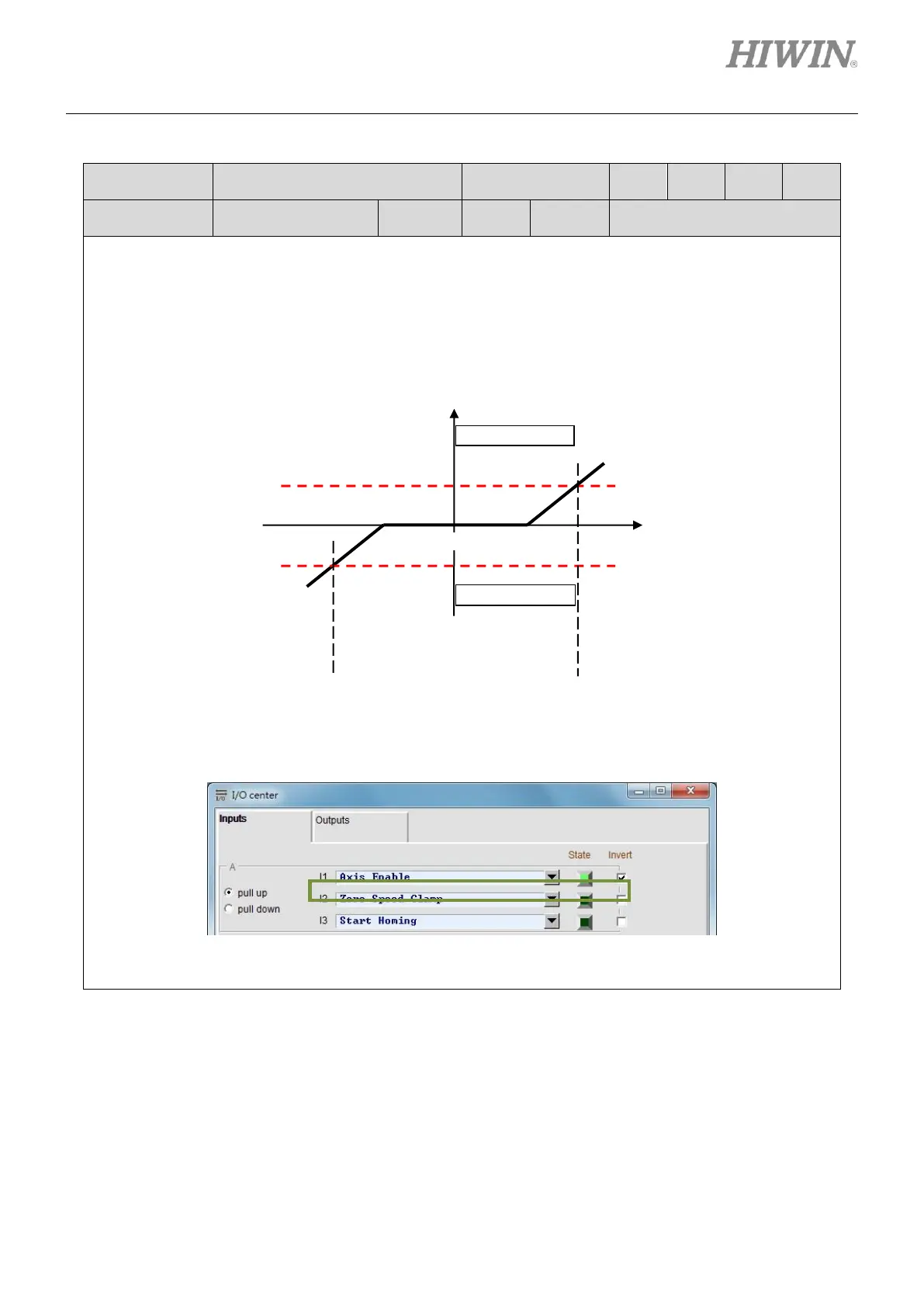
Set operation mode to velocity mode. Set one input to Zero Speed Clamp in I/O center. In the figure
below, I2 is set to Zero Speed Clamp.
Go to Protection center and set the velocity for activating brake (vel_stop). The default setting value is
500 count/s.