LCD Display D1 Servo Drive User Manual
7-32 HIWIN MIKROSYSTEM CORP.
(4) Electronic gear ratio setting
D1 servo drive provides two sets of electronic gear ratios. For detailed information, please refer to
section 5.4.1. The steps of setting electronic gear ratio are provided in table 7.6.1.7.
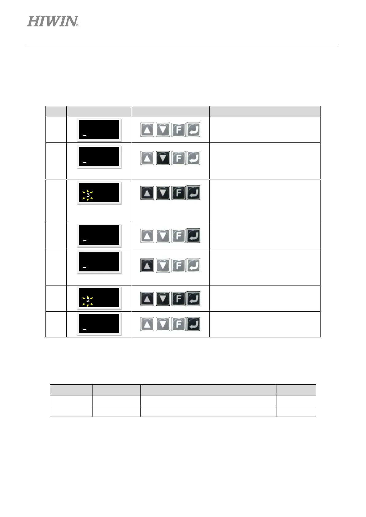
Table7.6.1.7
Continue from the setting page of
single-ended pulse signal and
differential pulse signal.
Press and hold Down key to go to
LCD No. 81 page (Refer to the note
below.) which is the setting page of
the numerator of electronic gear ratio
(output).
Press Enter key. Then change the
parameter from 1 to 3.
Note:
In this example, the gear ratio is set to 2:3.
Two input pulses equal three encoder
counts.
Press Enter key to complete the
setting of encoder count.
Press Up key once to go to LCD No.
82 page (Refer to the note below.)
which is the setting page of the
denominator of electronic gear ratio
(input).
Press Enter key. Then change the
parameter from 1 to 2.
Press Enter key to complete input
pulse setting.
Note:
Refer to the table below for the parameter settings of electronic gear ratio and pulse input method.
Table7.6.1.8
The numerator of electronic gear ratio (output)
The denominator of electronic gear ratio (input)