Procedure 2. Al Front Frame/Al8 CRT
4 PLACES
w47
(OPT 002)
W46
(OPT 002)
1
/
\
\
I
,W42
(STANDARD)
5J15
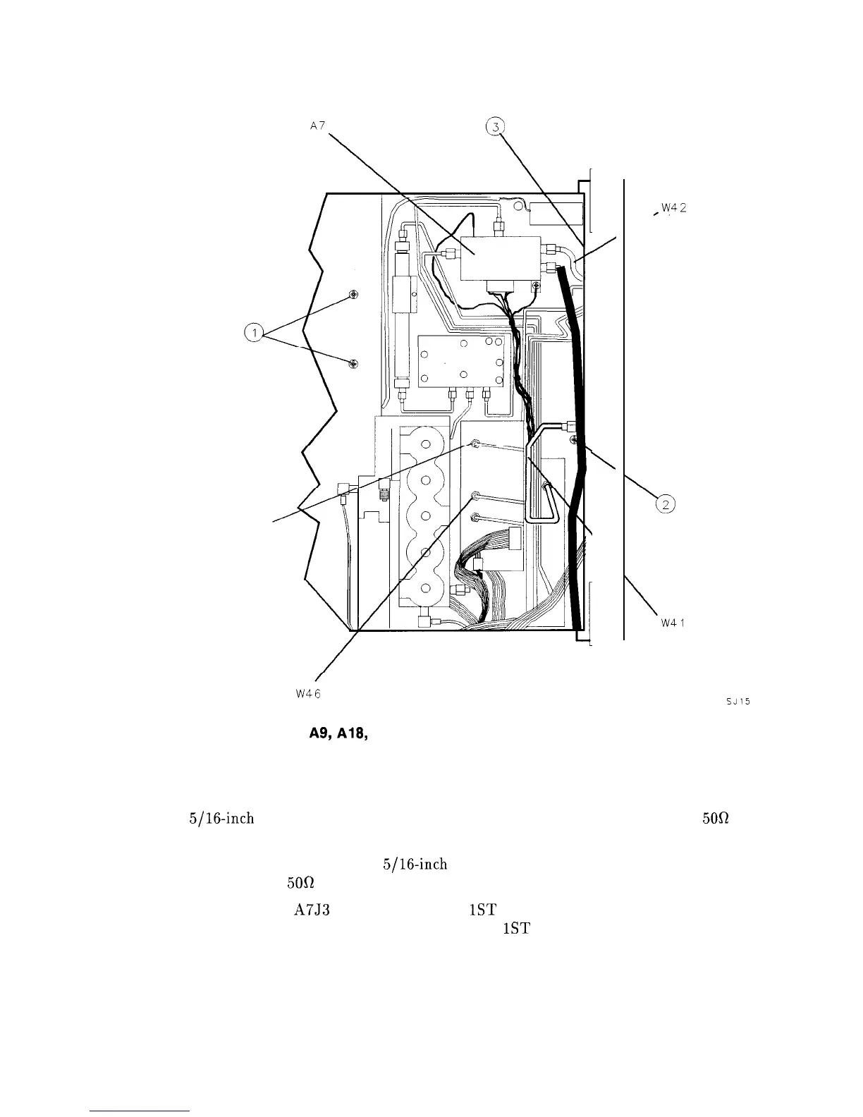
Figure 3-3.
A9,
A18, and Line-Switch Assembly Mounting Screws
16. Remove screw (2) securing the A9 Input Attenuator Assembly to the center support on
the front frame. See Figure 3-3.
17. Use a
5/16-inch
open-end wrench to disconnect W41 from the front-panel INPUT
50R
connector. Loosen the opposite end of W41.
18. For Option 002 analyzers: use a
5/16-inch
open-end wrench to disconnect W47 from the
front-panel RF OUT
50R
connector.
19. Disconnect W42 from A7J3 and the front-panel
1ST
LO OUTPUT connector. For Option
002 analyzers: disconnect W46 from the front-panel
1ST
LO OUTPUT connector.
20. Disconnect W36, coax 86, from the front-panel IF INPUT connector.
21. Remove the VOLUME knob and potentiometer from the front panel. If necessary, drill
out the nut driver used to remove the VOLUME potentiometer and cover the tip with
heatshrink tubing or tape to avoid scratching the enameled front panel.
3-6 Assembly Replacement