Procedure 2. Al Front Frame/Al8 CRT
22. Use a
9/16-inch
nut driver to remove the dress nut holding the front-panel CAL OUTPUT
connector to the front panel. If necessary, drill out the nut driver to fit over the BNC
connectors and cover the tip with heatshrink tubing or tape to avoid scratching the
enameled front panel.
23. Remove screw (3) securing the line-switch assembly to the front frame. See Figure 3-3.
24. Gently remove the line-switch assembly, using caution to avoid damaging
AlWl
and
power indicator LED
AlWlDSl.
25. Remove
AlWl
and AlWlDSl from the line-power switch assembly.
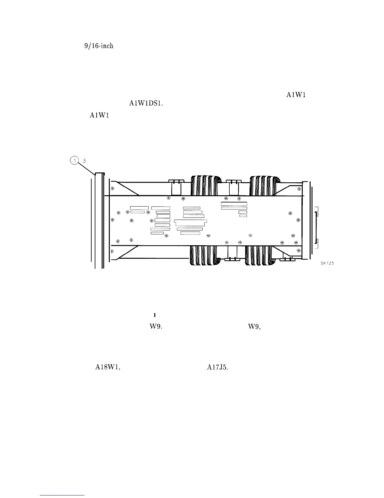
26. Remove the three screws (1) securing the front-frame assembly to the analyzer’s right side
frame. See Figure 3-4.
1 3 PLACES
q
Figure 3-4. Front-Frame Mounting Screws
27. Remove the three screws securing the front-frame assembly to the analyzer’s left side
frame.
28. Remove the four screws (1) (F’g
1
ure 3-3) securing the CRT clamps to the deck.
29. Pull the cable tie (1) to free W9. See Figure 3-5. Gently pry W9, the CRT cable, from
the end of the CRT assembly.
30. Support the Al8 CRT assembly while gently pulling the front frame and CRT ou of the
analyzer one or two inches.
31. Disconnect A18W1, the trace align wires, from A17J5. Remove the front-frame and CRT
assemblies.
32. Gently pull the CRT assembly off of the front-frame assembly.
Assembly Replacement 3-7