Procedure 2. Al Front Frame/Al8 CRT
AIAIWI
SK127
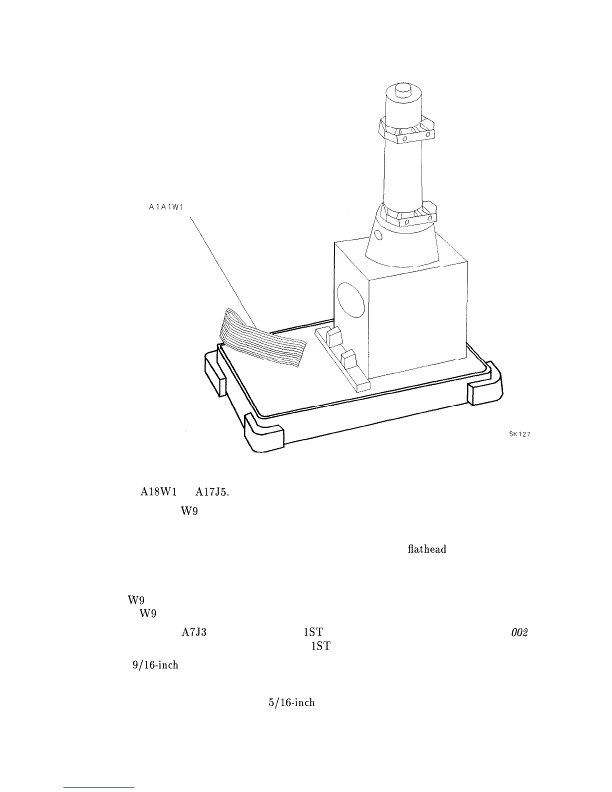
Figure 3-6. Placing the CRT into the Front Frame
5. Connect
A18Wl
to A17J5.
6. Snap CRT cable W9 onto the end of the CRT assembly.
7. Fully seat the front frame and CRT assemblies into the analyzer.
8. Secure the front frame to the analyzer’s side frames, using three
flathead
screws per side.
See Figure 3-4.
9. Retighten the four screws securing the CRT clamps to the deck.
10. Place W9 between the CRT assembly and the A6 Power Supply assembly top shield so
that the W9 wires are below the surface of the top shield.
11. Connect W42 to A7J3 and the front-panel
1ST
LO OUTPUT connector. For Option 002
analyzers: connect W46 to the front-panel
1ST
LO OUTPUT connector.
12. Use a
9/16-inch
nut driver to reconnect CAL OUTPUT connector to the front panel.
13. Connect the VOLUME potentiometer and knob to the front panel.
14. For Option 002 analyzers: use a
5/16-inch
open-end wrench to connect W47 to the
front-panel RF OUT connector.
Assembly Replacement 3-9